Radially Oriented Sintered NdFeB Ring Magnets: Sourcing, Multi-Pole Magnetization, and DFM Boundaries for Precision Motors & Robotics
Source radially oriented sintered NdFeB ring magnets: compare pole patterns, shaft retention, tooling costs, and inspection needs. Request a drawing review.
Published and technically reviewed: November 8, 2026. Audience: motor design engineers, robotics hardware leads, and global sourcing teams comparing radially oriented sintered NdFeB ring magnets with segmented rotors. Scope: preliminary selection and RFQ preparation; final dimensions, retention, magnetic performance, and delivery terms require project-specific supplier confirmation.
Radially oriented sintered NdFeB ring magnets replace multiple arc segments with one magnetic cylinder, reducing individual placement operations. They are worth evaluating when pole positioning, assembly repeatability, or rotor packaging limits your current design. A ring still needs a qualified shaft joint, magnetizing fixture, coating, and inspection process. A single-piece magnet does not by itself establish lower cogging torque or safe operating speed.
The first sourcing decision is whether you need a radially oriented blank with flexibility in subsequent magnetization, or a polar anisotropic design whose orientation is tailored to a particular pole pattern. Next, establish whether the supplier can produce your geometry, charge the intended pattern, and demonstrate the required waveform at the agreed measurement position.
This is a supplier-document-based engineering guide, not a report of Ganzhou Magnets rotor tests. The comparisons below are selection judgments; the worked cost and thermal calculations use explicitly hypothetical inputs. They are not quotations, capability guarantees, or measured customer outcomes. For an existing design, send your rotor drawing and operating conditions for review.
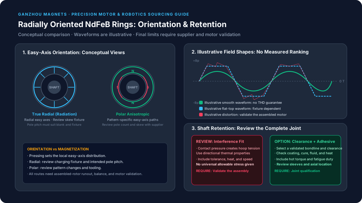
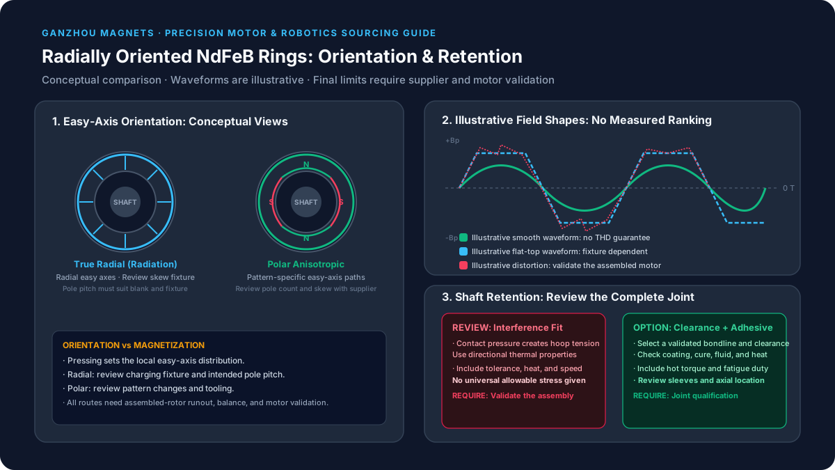
Figure 1: Conceptual orientation and retention comparison. Waveforms are illustrative, without measured amplitudes or a performance ranking. The drawing is not a manufacturing specification.
1. The Multi-Segment Assembly Bottleneck
A surface-mounted permanent magnet rotor assembled from separate arc tiles needs control of segment dimensions, adhesive thickness, angular placement, and curing fixtures. Each additional tile introduces another placement operation and another opportunity for variation. However, a well-controlled segmented rotor can perform well; changing the topology is a manufacturing decision that must be checked against the motor requirements.
1.1 Geometric and Adhesive Tolerance Stack-Up
Start with your actual tolerance budget. Identify the contributions from hub runout, magnet thickness, coating, adhesive bondline, and assembly fixture location. A ring removes tile-to-tile placement variation but introduces its own bore-to-OD relationship, roundness, coating variation, and mounting eccentricity. Specify the datum and inspection method alongside every critical tolerance. A small OD size tolerance does not establish assembled rotor runout.
1.2 Dynamic Rotor Unbalance at High RPM
Mass eccentricity creates a rotating force proportional to mass, eccentricity, and the square of angular speed. Eliminating individual tiles may simplify assembly, but an uneven bondline, sleeve, shaft, or eccentric bore can still create unbalance. Keep assembled-rotor balancing and overspeed qualification in the control plan. Do not infer a balance grade from the magnet's dimensional inspection alone.
1.3 Thermal Cycling and the Remaining Bonded Joint
A monolithic ring removes joints between adjacent magnet segments; it does not remove the ring-to-hub joint. Thermal expansion, adhesive cure shrinkage, moisture, and operating fluids still matter. Request compatibility evidence for the exact coating, adhesive, hub material, and temperature cycle. For a robotics drive that reverses repeatedly, include torque reversals and dwell conditions in joint validation rather than relying only on a room-temperature pull or shear result.
2. Orientation Physics: Compaction vs. Post-Sinter Magnetization
Do not conflate grain orientation during manufacture with pole charging after manufacture. The easy-axis distribution is established as part of the anisotropic material process. A later magnetizing pulse establishes magnetic polarity within that structure; it does not rotate the grain axes. Cutting a circular bore into an ordinary linearly oriented block therefore does not create a radially oriented blank.
An RFQ should identify the manufacturing route explicitly. Sintered, hot-deformed, and polymer-bonded rings are different products. A supplier's radial-ring photograph or generic NdFeB grade table does not establish that the quoted part uses the requested sintered process.
Orientation during powder processing
    -> sintering and subsequent heat treatment
    -> grinding and protective coating
    -> application-specific pulse magnetization
    -> dimensional, magnetic, and assembly qualification
The sequence above is conceptual. Charging before or after rotor assembly changes fixture access, handling, and qualification needs; confirm the proposed production sequence with the supplier.
2.1 True Radial (Radiation Oriented) Rings
The easy axes follow the radial direction around the circumference. This can allow multiple pole patterns and skew magnetization on a suitable blank. The practical limits still depend on ring dimensions, pole pitch, material, and fixture capability. Request evidence for the exact combination instead of treating “arbitrary pole count” as unlimited manufacturing capability.
2.2 Polar Anisotropic Rings
The orientation distribution follows magnetic paths associated with a particular pole pattern. Treat a pole-count change as a design and tooling review. Do not assume that a standard straight-pole product can be charged with an arbitrary helical skew; ask whether a purpose-designed skewed orientation or stacked arrangement is available.
Proterial's anisotropic ring overview distinguishes these two approaches. It describes radial designs with configurable charging and skew, and multi-pole anisotropic designs with near-sinusoidal surface fields. These are product-family descriptions, not a promise of any fixed flux improvement or motor-level THD.
3. Air-Gap Flux Density, Harmonics, and Cogging Torque
For motor and robotics engineers, a useful comparison specifies what is measured, where, and under which assembly conditions. Material remanence, free-space surface flux, installed air-gap flux, and winding back-EMF are different quantities. Comparing a catalogue remanence value with a Hall-probe reading can lead to the wrong grade or geometry decision.
3.1 Compare Like-for-Like Waveforms
For a radial scan, define probe distance from the coated OD, axial position, sensing direction, temperature, angular resolution, and whether back iron is installed. Request the raw angle-versus-field data as well as a plot. Different probe gaps can change both amplitude and harmonic content, making otherwise convincing supplier graphs unsuitable for direct comparison.
3.2 Translate Magnetic Measurements into Motor Requirements
Cogging depends on the complete rotor-stator geometry, including slot openings, pole count, air gap, eccentricity, and skew. Back-EMF also depends on winding distribution and speed. A smooth surface-field trace therefore cannot certify a motor torque-ripple target. Compare candidate rotors using the same electromagnetic model and a defined prototype test, with the motor team's acceptance criteria.
Skew may reduce selected harmonics while reducing useful fundamental flux or changing axial forces. Specify mechanical degrees across the active length and identify the harmonic being targeted. One stator-slot pitch is a possible design input, not a universal optimum.
4. Architectural Comparison Matrix
Use this matrix to decide which route deserves a quotation and prototype review. Entries are qualitative; no row substitutes for a supplier drawing approval or motor test.
| Evaluation metric | True radial sintered ring | Polar anisotropic sintered ring | Glued sintered arc segments | Bonded ring | Evidence to request |
|---|---|---|---|---|---|
| Orientation | Radial easy-axis distribution | Pattern-specific distribution | Defined for each segment | Isotropic or anisotropic, depending on process | Process declaration and orientation drawing |
| Pole-pattern changes | May reuse the blank with a different fixture | Reassess the orientation design | Reassess tile arrangement | Depends on material and charging | Feasibility for the proposed pole pitch |
| Skew | Fixture-dependent option | Product-design-dependent | Step arrangements are possible | Material- and fixture-dependent | Agreed skew definition and sample scan |
| Magnetic output | Depends on grade and geometry | Depends on orientation and geometry | Depends on tiles and assembled gaps | Binder content changes magnetic loading | Comparable field maps and motor model |
| Assembly | One ring needs alignment and retention | One ring needs alignment and retention | Multiple placement and bonding steps | Molding or separate mounting route | Actual cycle, cure, and inspection sequence |
| Balance | Must qualify the assembled rotor | Must qualify the assembled rotor | Must qualify the assembled rotor | Must qualify the assembled rotor | Assembly runout and balance report |
| Thermal suitability | Grade, demagnetizing field, coating, and joint matter | Same project-specific checks | Same checks plus segment joints | Binder and joint also matter | Hot demagnetization data and aging plan |
| Tooling investment | Compaction and charging needs vary | Orientation-specific tooling may be required | Cutting and assembly tooling vary | Molding and charging tooling vary | Itemized NRE, ownership, and revision terms |
| Corrosion | Protective system needs qualification | Protective system needs qualification | Coated edges and bonds need review | Binder does not guarantee sealing | Exposure-specific coating test |
| Design changes | Recheck geometry and charging | Recheck geometry, orientation, and charging | Recheck tiles and fixtures | Recheck mold and charging | Written change-control agreement |
For grade screening, use the NdFeB grades and temperature guide. Confirm availability in the selected ring process; a grade available as a block may be unavailable in your ring geometry.
5. Mechanical DFM: Shaft Retention and Hoop Stress
Sintered NdFeB is brittle. A generic metal-to-metal interference fit is a poor starting assumption for a ring magnet because internal contact pressure creates tensile hoop stress. Interference is not automatically impossible, but any such proposal needs material-specific analysis, tolerance control, and assembly validation. A slip fit with a qualified adhesive is a common alternative, not an automatic joint approval.
5.1 A Screening Equation, Not a Fit Specification
For an ideal isotropic elastic thick cylinder with internal pressure p and no external pressure, the bore hoop stress is:
sigma_theta_at_bore = p * (Do^2 + Di^2) / (Do^2 - Di^2)Here Do and Di are outside and inside diameters. Contact pressure is an input to this equation; it cannot be inferred from interference alone without shaft and ring stiffness, geometry, and boundary conditions. Radially oriented material is anisotropic, so this simplified model does not establish an allowable stress for a real ring. Include defects, coating, end effects, temperature, and speed in the final assessment.
5.2 Thermal Expansion Must Follow the Local Material Direction
Do not apply a single transverse or parallel expansion coefficient to every dimension of a radially oriented ring. The radial and circumferential directions relate differently to the local easy axis. Use supplier data and an appropriate anisotropic model for the bore response.
A hypothetical clearance sensitivity calculation illustrates the scale. Suppose a 30 mm interface has an effective shaft-minus-bore expansion difference of 8 micrometres per metre per kelvin over a 100 K rise:
Differential diametral growth = D * delta_alpha * delta_T
                            = 30 mm * 8e-6/K * 100 K
                            = 0.024 mm = 24 micrometres
This arithmetic shows why a room-temperature clearance alone is insufficient. The chosen expansion difference is an illustrative input, not a measured property of this article's ring. Arnold's N40 datasheet reports direction-dependent typical thermal properties and their validity intervals; those values require interpretation before use in a ring assembly.
5.3 Retention Review Points
Select the bondline from the adhesive supplier's guidance for the actual coating and substrate. Check transmitted torque, hot strength, fluid exposure, surface preparation, cure, fatigue, and manufacturing tolerance extremes. A published adhesive shear strength is not an allowable rotating-joint rating.
For a preliminary uniformly bonded cylindrical interface, average torsional shear scales as T / (2 * pi * r^2 * L). This estimate excludes end effects, defects, peel, aging, and dynamic loading. It can identify missing inputs; it cannot replace joint qualification. Axial shoulders address axial location but do not by themselves transmit torque or contain fragments. Sleeve and overspeed requirements depend on the complete rotor design, with no universal speed threshold.
6. Dimensional and Powder Metallurgy DFM Boundaries
There is no supplier-independent maximum OD, minimum wall thickness, or height limit for every radially oriented sintered ring. Tooling, orientation uniformity, grade, grinding allowance, and yield interact. Ask for a manufacturing review of the actual drawing rather than copying a generic capability table into the purchase specification.
| Drawing input | Define in the RFQ | Manufacturing question | Qualification evidence |
|---|---|---|---|
| OD and ID | Finished dimensions, coating included or excluded | Can both surfaces be finished with adequate stock? | Dimensional first-article report |
| Wall thickness | Nominal wall and tolerance extremes | Is pressing, handling, and grinding yield acceptable? | Supplier feasibility statement |
| Axial height | Active length and end geometry | Is orientation consistent through the full length? | Field scans at agreed axial planes |
| Bore datum | Functional locating surface and datum scheme | How is the ring held during inspection? | Inspection setup description |
| Runout | Surface, datum axis, and assembled condition | Which contributors belong to magnet versus assembly? | Part and rotor measurement plan |
| Edge treatment | Chamfer or radius, permissible chips | Will grinding and plating preserve edges? | Visual acceptance examples |
| Coating | Type, thickness, coverage, and exposure | Does it affect fit and adhesive compatibility? | Coating and bonding qualification |
| Stacked rings | Axial gaps, clocking, and total length | How are pole transitions aligned between rings? | Stacked-assembly scan |
For context only, Proterial lists recommended radial-ring diameters of 15–90 mm and lengths of 5–60 mm; its multi-pole examples use 8–43 mm and 5–40 mm. These recommendations describe that manufacturer's product family. They neither establish Ganzhou Magnets capacity nor prohibit a different supplier route outside those ranges.
For a long active stack, compare a single ring with multiple shorter rings. Stacking adds axial seams, clocking requirements, and assembly work, so it also needs magnetic and mechanical validation. Prepare an RFQ package once the drawing datums, process route, and operating conditions are defined.
7. Tooling Economics and Sourcing ROI Framework
Compare cost per accepted assembled rotor over a defined program quantity. A lower magnet piece price can be outweighed by assembly labor, cure time, inspection, balancing, or yield. Conversely, a monolithic ring can have a higher magnet price while simplifying assembly. Neither outcome should be assumed before obtaining comparable quotations.
7.1 Separate Recurring Cost from NRE
Request separate lines for orientation tooling, grinding fixtures, magnetizing fixtures, sample qualification, and recurring inspection. Clarify tool ownership, maintenance, life, storage, and the charge for a pole-count or skew revision. Include coating, packaging, freight, duties, currency assumptions, and delivery terms when comparing global suppliers.
7.2 A Reproducible, Hypothetical Crossover Example
The following numbers are invented planning inputs, not market benchmarks or Ganzhou Magnets prices. Assume both routes meet the same approved motor requirements, and their recurring costs include agreed yield allowances.
| Cost input | Segmented route | Ring route |
|---|---|---|
| Upfront tooling and qualification | USD 3,000 | USD 22,000 |
| Recurring accepted-rotor cost | USD 23.55 | USD 19.24 |
Additional NRE = 22,000 - 3,000 = USD 19,000
Recurring saving = 23.55 - 19.24 = USD 4.31 per accepted rotor
Break-even quantity = 19,000 / 4.31 = 4,408.35
Round up: 4,409 accepted rotors
This is a cumulative program quantity, not an annual-volume rule. At 2,000 accepted units per year, simple undiscounted payback would be about 2.2 years if all assumptions hold. If recurring savings fall to USD 2.00, the same incremental investment needs 9,500 accepted units. If savings are zero or negative, there is no cost crossover under this model. Consider financing, requalification, inventory, and schedule risks separately before approval.
7.3 Ask for Milestones Instead of a Universal Lead Time
Separate feasibility review, tool design, tool fabrication, sample manufacture, field mapping, customer approval, and production ramp. Specify when the clock starts and which customer inputs can stop it. Prototype delivery is not proof of recurring capacity. Obtain written sample and production schedules rather than assuming a standard number of weeks for every ring.
8. Quality Control and 360-Degree Rotary IQC Protocol
A single surface-gauss reading cannot demonstrate every pole's amplitude, pitch, and skew. Bulk material characterization also serves a different purpose from spatial mapping of a finished multi-pole ring. Agree a qualification plan that covers material, geometry, magnetic pattern, coating, and the mounted assembly.
8.1 Rotary Hall-Probe Mapping
Use a repeatable mounting datum and control probe lift-off. Record sensor calibration, range, sensitive-axis direction, temperature, angular sampling, and axial location. A 0.50 mm radial stand-off can be a proposed test condition, but it is not a universal standard. Skewed rings need measurements at multiple axial planes or an equivalent agreed mapping method.
Keep raw data, drawing revision, lot identity, fixture identity, and analysis settings together. Re-measure representative parts after mounting when the rotor core or sleeve changes the field. A magnetic scan does not prove the absence of internal cracks; mechanical integrity requires its own agreed inspection and validation.
8.2 Define Metrics Before Setting Limits
- Pole amplitude spread: use magnitudes of the positive and negative peaks consistently. One possible definition is
(maximum peak magnitude - minimum peak magnitude) / mean peak magnitude * 100%. This nonnegative spread should not be written as a plus/minus limit. - Pole pitch: state whether angles are mechanical or electrical. For
Pequally spaced poles, nominal pitch is360/Pmechanical degrees. Define the datum and treatment of zero-crossing noise. - Harmonics: identify the intended fundamental spatial order, sampling, windowing, and highest included order. Surface-field THD and back-EMF THD require separate acceptance definitions.
- Area balance: define how positive and negative field areas are integrated and normalized. Match the tolerance to motor sensitivity and measurement repeatability.
There is no universal 3% peak-spread or 2.5% THD limit for all robotics rings. Set limits through design analysis, prototype results, and a capable inspection process, then define lot sampling and change control in the purchase agreement.
9. Sourcing and Engineering RFQ Checklist
Use this checklist to make competing quotations technically comparable before discussing a unit-price target.
- Process and orientation: sintered material route, true radial or polar anisotropic design, and permitted alternatives.
- Pole pattern: pole count, polarity drawing, angular datum, mechanical skew, and axial mapping positions.
- Geometry: OD, ID, height, coating allowance, chamfers, datums, and functional runout requirements.
- Grade and thermal duty: hot demagnetization curves, peak and continuous temperatures, opposing field, and irreversible-loss criterion.
- Retention: hub and sleeve materials, tolerance stack, adhesive process, torque duty, and rotor speed envelope.
- Environment: fluids, humidity, corrosion test method, duration, and pass criteria for the exact coating system.
- Magnetic acceptance: measurement gap, back-iron condition, scan settings, metric definitions, and agreed limits.
- Quality records: first-article report, raw waveform files, calibration traceability, lot identity, and sampling plan.
- Commercial scope: itemized NRE, tool ownership, accepted-part costing, annual and lifetime quantities, schedule milestones, and revision charges.
- Delivery state: magnetized or unmagnetized, packaging, receiving capability, and transport assessment for the packaged shipment.
10. Frequently Asked Questions (FAQ)
Can we machine a radial sintered ring from a solid sintered block?
Machining changes shape, not the easy-axis distribution. A conventional linearly oriented block will not become a true radial blank when a bore is cut into it. Ask for the orientation drawing and process declaration rather than accepting “ring magnet” as a sufficient description.
Does polar anisotropy guarantee higher motor torque or lower cogging?
No. It offers a different orientation design, but motor torque and cogging depend on the installed magnetic circuit, winding, slots, air gap, and control conditions. Compare supplier field maps under matching conditions, then validate the candidate in the motor model and prototype.
Can a polar anisotropic ring use a different pole count or skew?
Its orientation is designed around a particular pattern. A change needs supplier review and may need new tooling. Treat skew as a product-specific capability; avoid both assuming an ordinary blank supports it and claiming that every purpose-designed polar product is physically incapable of skew.
What minimum wall thickness can Ganzhou Magnets supply?
This guide does not establish a verified company capability limit. Submit OD, ID, length, grade, coating, and tolerances for a manufacturability review. Ask the quotation to identify any prototype-only dimension, production-yield risk, or proposed geometry change.
How do we prevent rotation without a press fit?
A qualified adhesive joint is one option. Its design must account for torque, temperature, bond area, coating adhesion, cure, fluid exposure, and fatigue. Choose clearance from the complete tolerance and thermal analysis. Neither a generic micrometre gap nor a catalogue adhesive strength establishes safe torque capacity.
What is the lead time for tooling and first samples?
It depends on tooling complexity, supplier capacity, material availability, and the qualification scope. Request dated milestones for tooling release, first articles, magnetic inspection, and production approval. Agree responsibility for delays caused by drawing or pole-pattern changes.
Should we ship rings unmagnetized?
This can simplify handling and reduce magnetic interaction, provided the receiving site has a validated charging fixture and inspection process. Residual field and the final packaged shipment still need assessment. Do not assume that unmagnetized delivery automatically removes all transport requirements or guarantees zero attraction.
11. Related Engineering Pages & Product Resources
- Custom Neodymium Magnets
- Neodymium Magnets for Electric Motors
- NdFeB Magnet Grades & Temperature Ratings
- Post-Assembly Magnetization for PM Rotors Sourcing Guide
- High-Speed PM Rotor Sleeve Retention Guide
- Laminated NdFeB Magnets for High-Speed Motors
- NdFeB Magnet Machining Tolerances & DFM Guide
- Generate an Online Permanent Magnet RFQ
12. Sources and Technical Reference Boundaries
Public sources below were reviewed on November 8, 2026. They support the material and orientation discussion within the stated scope. They do not certify Ganzhou Magnets capability, validate a rotor design, or establish the hypothetical costs in Section 7.
| Source | Supports | Boundary |
|---|---|---|
| Proterial: Nd-Fe-B High-Performance Anisotropic Ring Magnets | Radial versus multi-pole orientation and manufacturer-specific recommended geometries | Product-family guidance; not a universal performance or manufacturing limit |
| Arnold Magnetic Technologies: Neodymium Iron Boron Magnets | Grade-dependent magnetic properties, temperature considerations, and protective coatings | Grade tables do not approve a particular ring, joint, or motor |
| Arnold: N40 Sintered NdFeB Datasheet, revision 210607 | Direction-dependent typical material properties and measurement-temperature intervals | N40 material reference; not a radial-ring stress allowable or a high-temperature grade approval |
Evaluating a transition from discrete arc segments to radially oriented sintered NdFeB rings? Contact Ganzhou Magnets with your rotor drawing, pole pattern, operating temperature, speed, and expected quantity to request a feasibility review and a quotation with explicit assumptions.
Author

Categories
More Posts
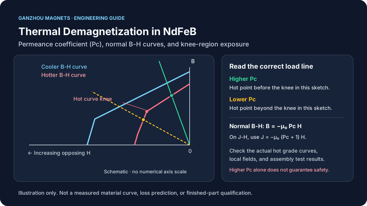
Thermal Demagnetization in NdFeB: Permeance Coefficient (Pc), Load Lines, and Irreversible Loss Prevention
Prevent NdFeB thermal demagnetization: understand permeance coefficient (Pc), read load lines, and use an RFQ checklist to request a magnet grade review.

NdFeB vs SmCo: Guía completa de comparación de imanes para ingenieros
Comparación detallada de imanes de neodimio (NdFeB) y samario-cobalto (SmCo) que cubre rendimiento magnético, estabilidad térmica, resistencia a la corrosión, costo y recomendaciones por aplicación.

Rare Earth Permanent Magnets Market Update (2026-W18): Derivative Tariff Corrections Add a New Compliance Gate
Week 18 rare earth magnets update: U.S. derivative-duty corrections, NdFeB and Sm supply signals, and immediate sourcing actions for US, EU, and LATAM buyers.