NdFeB Magnet Machining Tolerances: Cost Drivers and DFM Guidelines
NdFeB magnet machining tolerances guide for DFM: compare ±0.1mm, ±0.05mm, and ±0.01mm cost drivers, coating stack-ups, RFQ actions, and buyer quote limits.
Snapshot date: June 24, 2026. One of the most common reasons custom neodymium (NdFeB) magnet quotes come back 2x to 3x higher than expected is over-specified dimensional tolerances. Mechanical engineers often default to standard metal-machining tolerances (e.g., ±0.01mm or ISO 2768-m) without realizing that NdFeB is a brittle, sintered ceramic. This guide details the manufacturing reality of magnet machining, the true cost of tight tolerances, and how to optimize your drawings for procurement.
Scope: This is a Design for Manufacturing (DFM) and cost-optimization guide for mechanical engineers, electric motor designers, and procurement teams sourcing custom sintered NdFeB magnets. It covers dimensional tolerances, machining methods, scrap rate economics, and coating thickness stack-ups.
When transitioning from a CAD model to a physical magnetic assembly, the easiest mistake to make is treating a sintered Neodymium Iron Boron (NdFeB) magnet like a piece of 304 Stainless Steel or Aluminum.
It is not.
Sintered NdFeB is an intermetallic compound. Mechanically, it behaves much more like a fragile tea cup than a block of steel. It has an exceptionally high Vickers hardness (typically 550–600 HV) but extremely low tensile strength and high brittleness. You cannot mill it, drill it with standard high-speed steel bits, or turn it on a standard lathe. It must be ground with diamond-coated abrasives or cut with Electrical Discharge Machining (EDM).
Every time an engineer tightens a tolerance on a magnet drawing from ±0.05mm to ±0.02mm, they are fundamentally changing the manufacturing process required to produce that part, often drastically increasing the cycle time and the scrap rate.
This guide provides a comprehensive framework to balance your assembly's precision requirements with the realities of magnet mass production. If you have a drawing ready, send it to Ganzhou Magnets for a free DFM review before locking your final specifications.
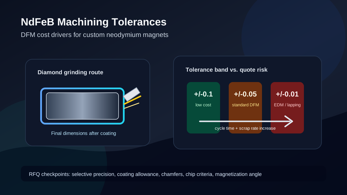
The industry standard for cost-effective mass production of basic blocks and discs.
Demanding ±0.02mm requires Wire EDM and hand-grinding, multiplying unit costs.
Ni-Cu-Ni plating adds measurable thickness that must be accounted for in the raw block size.
Brittle edges chip easily during tight-tolerance grinding, destroying the yield rate.
The Material Reality: Why NdFeB is Hard to Machine
To understand why tolerances drive cost, you must understand the material structure. Sintered NdFeB is created through powder metallurgy. Nd, Fe, B, and heavy rare earth elements (like Dysprosium or Terbium) are melted, milled into a microscopic powder, pressed in a magnetic field, and then baked (sintered) in a vacuum furnace.
The resulting block is fully dense but highly susceptible to mechanical shock.
- High Hardness vs. Low Toughness: The material is hard enough to wear out standard carbide tooling in minutes. Therefore, all machining must be abrasive—using diamond wheels, diamond wire saws, or core drills. Because it is brittle, high tool pressure causes microscopic cracks or immediate edge chipping.
- Thermal Sensitivity: During grinding, friction generates intense heat. If this heat exceeds the magnet's Curie temperature, the surface layer becomes permanently demagnetized. Therefore, all machining must be done under a flood of specialized coolant.
- Oxidation Risk: The iron and neodymium in the alloy oxidize rapidly when exposed to air and moisture. The cooling fluid must contain rust inhibitors, and the machining process must move swiftly into plating to prevent deep-set corrosion.
The Cost Multiplier Effect of Tolerances
When a factory receives an RFQ (Request for Quotation), the engineering team looks at the drawing's tolerance block before they even look at the material grade. The tolerance dictates the machine routing.
Tier 1: Standard Commercial Tolerance (±0.05 mm to ±0.1 mm)
This is the "sweet spot" for 80% of industrial and commercial applications.
- Method: Multi-wire diamond saws and high-throughput double-disk grinders.
- Economics: Hundreds of magnets can be sliced simultaneously from a large master block. The abrasive wear is predictable, and the process is highly automated.
- Use Case: Magnets glued into pockets, magnetic separators, speakers, standard consumer electronics.
Tier 2: High Precision (±0.03 mm to ±0.04 mm)
- Method: Requires secondary processing. After slicing, the magnets are moved to precision surface grinders or centerless grinders (for cylinders).
- Economics: Increases labor and machine time. The yield drops slightly because the extra handling and secondary grinding passes increase the risk of chipping the brittle corners.
- Use Case: High-speed electric motor rotors (where mass imbalance causes vibration), tight press-fit assemblies, precision voice coil motors (VCM).
Tier 3: Extreme Precision (±0.01 mm to ±0.02 mm)
- Method: Slow-feeding Wire Electrical Discharge Machining (Wire-EDM) or extremely slow, multi-pass precision lapping.
- Economics: Costs skyrocket. Wire EDM cuts one piece at a time at a glacial pace compared to diamond saws. The scrap rate is severe because any microscopic internal stress released during cutting can cause a ±0.01mm part to warp out of tolerance. You are paying for the factory to throw away the parts that didn't make the cut.
- Use Case: Aerospace actuators, critical optical sensors, medical devices (MRI components), specialized Halbach arrays requiring perfect zero-gap fitting.
The Coating Stack-Up Problem
This is the number one reason custom magnets fail Incoming Quality Control (IQC) at the buyer's facility.
Sintered NdFeB will rust into powder if left uncoated. Therefore, almost all magnets receive a surface treatment—most commonly a Nickel-Copper-Nickel (Ni-Cu-Ni) electroplating or an Epoxy spray.
Tolerances apply to the FINAL, coated dimensions.
If your drawing specifies a block that is exactly 10.00 mm ±0.05 mm, the factory must machine the raw, uncoated NdFeB block to approximately 9.96 mm to account for the plating.
Here is the DFM impact of coating choices on tolerances:
| Coating Type | Typical Thickness (per surface) | Impact on Dimension (Diameter/Width) | DFM Machining Implication |
|---|---|---|---|
| Passivation / Phosphate | < 2 µm | Negligible (< 0.004 mm) | Factory machines to near-net shape. Best for glued-in motor magnets. |
| Ni-Cu-Ni (Nickel-Copper-Nickel) | 10 µm - 20 µm | Adds 0.02 mm to 0.04 mm total | Plating thickness varies slightly at edges (dog-bone effect). Tight tolerances are harder to hold consistently. |
| Zinc (Zn) | 8 µm - 15 µm | Adds 0.016 mm to 0.03 mm total | Thinner than Nickel, slightly easier to hold tight tolerances, but less corrosion resistant. |
| Epoxy (Spray) | 15 µm - 30 µm | Adds 0.03 mm to 0.06 mm total | Spray coatings pool slightly in corners. Very difficult to hold ±0.02mm on an epoxy-coated part. |
| Parylene-C | 10 µm - 15 µm | Adds 0.02 mm to 0.03 mm total | Vapor deposition provides highly uniform thickness, ideal for tight precision on medical parts, but highly expensive. |
| Ni-Cu-Ni + Epoxy | 25 µm - 40 µm | Adds 0.05 mm to 0.08 mm total | Useful for harsh environments, but it consumes most of a ±0.05mm drawing tolerance unless the raw magnet is undersized carefully. |
Critical Engineering Warning
The "Dog-Bone" Plating Effect
In electroplating (like Ni-Cu-Ni), the electrical current density is highest at the sharp corners and edges of the magnet block. This means the nickel deposits thicker on the edges than in the center of the flat face—a phenomenon known as the "dog-bone" or "bathtub" effect. If you require a strict ±0.02mm flatness across a wide face, electroplating will almost certainly push the edges out of spec. DFM Solution: Chamfer or heavily radius the edges to reduce current density, or switch to a uniform vapor deposition coating like Parylene if extreme precision is required.
Shape Complexity and Tolerance Interaction
The geometric shape of the magnet dictates the machining method, which in turn sets the floor for how tight your tolerances can realistically be without exponentially increasing costs.
Blocks, Cubes, and Rectangles
- Standard: ±0.05 mm.
- DFM Note: These are the cheapest to hold tolerances on because they can be cut using multi-wire saws and finished on massive, flat double-disc grinders. If you only need one dimension to be highly precise (e.g., the thickness for a magnetic gap), specify ±0.02mm only for the thickness, and leave the length/width at ±0.1mm.
Cylinders and Discs
- Standard (Diameter): ±0.05 mm.
- DFM Note: The outer diameter (OD) is finished using centerless grinding, which is highly efficient. Tighter tolerances (±0.03mm) on the OD are more affordable than tight tolerances on blocks. However, the thickness (cut face) should remain at ±0.05mm.
Rings and Tubes
- Standard (OD/ID): ±0.05 mm to ±0.1 mm.
- DFM Note: Rings are notoriously difficult. The Inner Diameter (ID) must be core-drilled. If the wall thickness (OD minus ID) is very thin (less than 1.5mm), the magnet becomes incredibly fragile. Specifying tight tolerances on a thin-walled ring guarantees a massive scrap rate because the ring will fracture from the vibrations of the grinding wheel. DFM Rule: Ensure your wall thickness is at least 1.5mm, and allow ±0.1mm on the ID if possible.
Arc Segments (Motor Magnets)
- Standard: ±0.05 mm for outer/inner radius.
- DFM Note: Motor arcs are usually cut via wire EDM or specialized profile grinding. Because they must nest precisely into a rotor slot or onto a surface, engineers often demand extreme precision. A smarter DFM approach is to design the rotor pocket with a slightly larger tolerance and use a high-strength structural adhesive (epoxy) to fill the gap and secure the magnet. The cost of the extra glue is pennies; the cost of a ±0.02mm arc magnet is dollars.
For more details on complex shapes, review our guide on custom neodymium magnets.
The Scrap Rate Economics: Why Buyers Pay for Broken Magnets
When you receive a quote for 10,000 magnets, you are not just paying for 10,000 good pieces. You are paying for the raw material and labor required to yield 10,000 good pieces.
Because NdFeB is brittle, the act of machining induces micro-stresses. As grinding wheels wear down, they exert more pressure on the part. At the very edge of the magnet, this pressure causes a "chip."
Most quality control standards (like the common AQL criteria for magnets) allow for microscopic edge chips that do not affect the magnetic volume. However, if an engineer marks a drawing with ALL SURFACES MUST BE PERFECTLY SMOOTH, NO CHIPS ALLOWED, combined with a ±0.02mm tolerance, the factory has to visually inspect every single piece under magnification and throw away any magnet with a 0.1mm chip.
If the factory has to make 20,000 magnets to yield 10,000 perfect ones, your unit price doubles.
DFM Solution: Clearly define allowable chip sizes on non-critical edges. A common standard is "Edge chips ≤ 0.5mm long and ≤ 0.2mm deep are acceptable provided they do not expose the bare magnet to corrosion."
Magnetic Alignment and Dimensional Tolerances
A frequently overlooked aspect of tolerance design is the relationship to the magnetic field. A magnet is dimensionally measured with calipers; it is magnetically measured with a Gaussmeter or Fluxmeter.
If you specify a very tight dimensional tolerance but fail to specify the tolerance on the angle of magnetization, your assembly might still fail. During the pressing stage of manufacturing, the powder is aligned by a magnetic field. This alignment (the "c-axis") can wander by 1 to 3 degrees.
If you are building a precision Hall-effect sensor assembly, a dimensionally perfect magnet that has a 3-degree angular deviation will throw off your sensor readings.
Related Engineering References
Use these internal pages to convert the tolerance decision into a complete RFQ package:
- Machining and tolerances for NdFeB magnets explains the baseline manufacturing route for blocks, discs, rings, and arcs.
- NdFeB coatings: nickel, zinc, epoxy, and parylene helps align coating thickness with final dimensional tolerance.
- RFQ checklist for drawings, grades, and coatings lists the drawing notes buyers should send before quote comparison.
- Magnet coatings and surface treatments guide compares corrosion protection, salt-spray expectations, and dimensional budget.
- Laminated NdFeB magnets for high-speed motors covers a related case where magnet segmentation, adhesive gaps, and tolerances interact.
Engineering & Procurement DFM Checklist
Before submitting your RFQ for custom magnets, run through this checklist to strip out unnecessary costs.
- Challenge Every Zero: Does this dimension really need to be ±0.02mm? Can the mechanical assembly be redesigned to absorb a ±0.05mm or ±0.1mm variation using adhesives or spring-clips?
- Selective Precision: Apply tight tolerances only to the critical mating surfaces. Leave non-mating dimensions at ±0.1mm.
- Account for Plating: Explicitly state on the drawing:
Tolerances apply AFTER plating.Ensure your design accounts for the 15-20µm thickness of Ni-Cu-Ni or Epoxy. - Design in Chamfers: Sharp 90-degree corners chip easily and cause uneven electroplating. Specify a 0.2 x 45° or R0.2 chamfer on all edges to dramatically improve factory yield and coating uniformity.
- Define Acceptable Defects: Include a note defining acceptable visual defects (e.g., "Max edge chip 0.3mm"). Do not demand zero-defect cosmetics unless strictly necessary.
- Review Aspect Ratios: Avoid designing magnets where the thickness is less than 10% of the length/width. Broad, paper-thin magnets (e.g., 50 x 50 x 1 mm) will warp and break during machining, making tolerances impossible to hold.
- Consult the Factory Early: The best way to reduce cost is to send your preliminary CAD to the magnet manufacturer and ask: "Which dimension is driving the cost up?"
Frequently Asked Questions (FAQ)
What is the tightest tolerance possible for NdFeB magnets?
Using precision slow-wire EDM and temperature-controlled lapping, it is technically possible to hold ±0.005 mm (5 microns). However, this is strictly limited to small, specialized aerospace or medical components, and the cost can be 10x to 20x higher than a standard magnet.
Why did my magnets arrive out of tolerance after sitting in storage?
If the coating was compromised and the magnet began to oxidize, the NdFeB material swells as it rusts. What measured 10.00mm out of the factory might measure 10.05mm months later if micro-corrosion has set in beneath the plating.
Does the magnetic grade (e.g., N35 vs N52) affect machining tolerances?
Slightly. Higher energy grades (like N52) and high-temperature grades (like N45UH) have different ratios of Dysprosium and Cobalt, which subtly change the brittleness of the sintered block. However, for standard ±0.05mm tolerances, the grade does not change the machining capability. For extreme precision, high-Dysprosium materials can be slightly tougher, reducing chipping during grinding.
Can I machine or modify the magnet myself after receiving it?
No. First, grinding NdFeB destroys the protective coating, guaranteeing rapid corrosion. Second, the dust generated is highly flammable and toxic. Third, unless you use diamond tooling and continuous coolant, you will shatter the magnet or thermally demagnetize it.
If I buy unmagnetized blocks, are they easier to machine?
Yes. All factory machining is done before the magnets are magnetized. Machining a magnetized block is nearly impossible because the magnetic swarf (metal dust) instantly sticks to the workpiece and the tooling, destroying the grinding wheel and the surface finish.
How do chamfers reduce the cost of the magnet?
Chamfers (beveled edges) do two things: they remove the fragile sharp corner that is prone to chipping during tumbling and handling (reducing scrap rate), and they eliminate the high-current-density points during electroplating, ensuring a more uniform coating thickness.
Sources and Further Reading
The tolerance benchmarks and DFM guidelines in this article are synthesized from published magnet-manufacturing guidance, coating data, and ASTM standard scope notes. Source pages were evaluated during this review on June 24, 2026.
| Source | Relevance & Data Point | URL |
|---|---|---|
| Amazing Magnets: Magnet Tolerance & Geometry Limitations | Gives practical permanent-magnet tolerance limits, brittle-shape warnings, and machining method constraints including diamond grinding, coring, chamfering, and wire EDM. | View Source |
| e-Magnets UK: How Neodymium NdFeB Magnets Are Made | Describes the NdFeB manufacturing flow, machining after sintering, use of diamond tools and EDM, standard ±0.1mm tolerance, achievable ±0.05mm tolerance at extra cost, and 15-35 µm Ni-Cu-Ni plating. | View Source |
| e-Magnets UK: Neodymium Coatings | Explains why uncoated NdFeB corrodes, identifies Ni-Cu-Ni as the standard protective coating, and lists coating options including epoxy, zinc, parylene, PTFE, and combination coatings. | View Source |
| ASTM WK93030 / A1101-23 Work Item | Confirms the ASTM A1101-23 scope for sintered and fully dense NdFeB permanent magnets and the 2023 revision context for commercially available classifications. | View Source |
Are your custom magnet costs too high? The issue might be hidden in your CAD drawing's tolerance block. Contact Ganzhou Magnets' engineering team for a comprehensive DFM review to optimize your design for mass production and lower your unit costs.
Author

Categories
More Posts
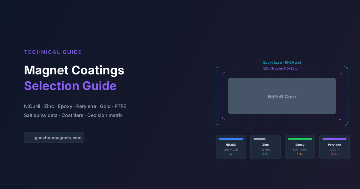
Magnet Coatings and Surface Treatments: Complete Selection Guide
In-depth comparison of NdFeB magnet coatings — NiCuNi, zinc, epoxy, parylene, gold, and PTFE. Includes salt spray data, cost tiers, thickness impact, and application-specific recommendations.
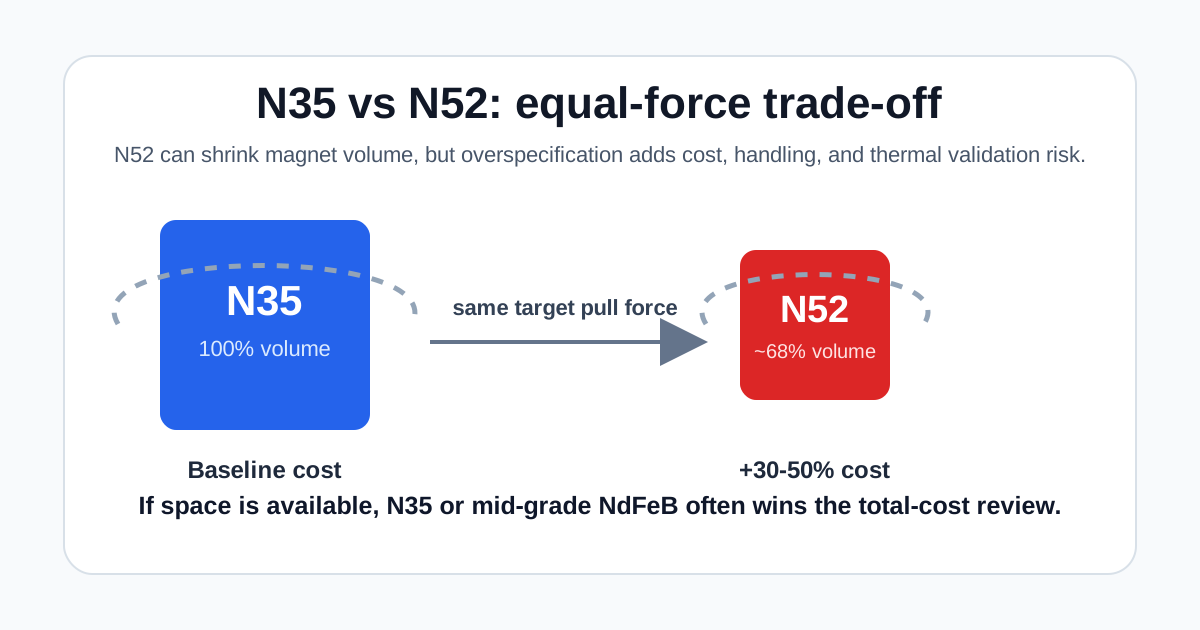
N35 vs N52 Neodymium Magnets: The Hidden Costs of Over-Specification
A comprehensive guide for engineers and procurement teams comparing N35 and N52 neodymium magnets. Learn how to avoid the hidden costs of over-specification.

Reducing Heavy Rare Earth Costs: The 2026 Buyer's Guide to Grain Boundary Diffusion (GBD) NdFeB Magnets
A comprehensive guide for engineers and procurement teams on using Grain Boundary Diffusion (GBD) to reduce Dysprosium (Dy) and Terbium (Tb) costs in high-temperature NdFeB magnets.