Laminated NdFeB Magnets for High-Speed Motors
Laminated NdFeB magnets guide for high-speed motors: compare eddy current loss, slice thickness, QA tests, cost trade-offs, and RFQ specs. Contact us.
Snapshot date: June 23, 2026. As electric vehicle (EV) traction motors push beyond 20,000 RPM and industrial aerospace actuators demand higher efficiency, thermal management of NdFeB magnets has become a critical engineering bottleneck. This guide details when to specify laminated magnets, the physical mechanism of eddy current reduction, and the cost implications for procurement teams.
Scope: this is a design-for-manufacturing and procurement guide for buyers specifying sintered laminated NdFeB magnets for high-speed motors, generators, spindle drives, and compact servo systems. It does not replace motor FEA, rotor spin testing, or adhesive qualification, but it gives engineering and sourcing teams the RFQ boundaries needed before supplier quoting.
In high-performance electric motors, the rotor is subjected to high-frequency, alternating magnetic fields from the stator. Because Neodymium Iron Boron (NdFeB) is an electrically conductive metal alloy, these changing fields induce closed-loop electrical currents within the solid magnet body.
These are known as Eddy Currents.
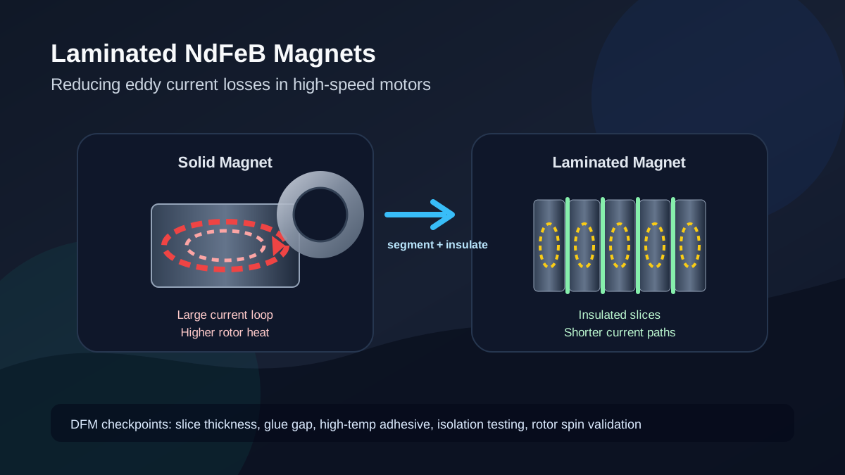
Due to the internal electrical resistance of the NdFeB material, eddy currents generate rapid Ohmic heating. If the motor operates at high speeds, this localized heat can easily push the magnet past its maximum operating temperature, resulting in irreversible thermal demagnetization. To solve this, engineers use Laminated NdFeB Magnets—segmenting the solid block into thin slices separated by microscopic insulating layers to break the conductive path.
This guide provides a comprehensive framework for buyers and engineers to evaluate, price, and source laminated magnets effectively in 2026. We will explore the manufacturing complexities, cost-benefit trade-offs, and rigorous quality assurance protocols necessary to ensure these critical components perform flawlessly under extreme stress.
If your team already has a rotor drawing, target RPM, grade, and inverter switching frequency, send the specification to Ganzhou Magnets for a DFM review before you lock the slice count.
Proper lamination can eliminate the vast majority of eddy current losses compared to a solid magnet.
Advanced epoxy layers are kept extremely thin to maximize the magnetic volume ratio (fill factor).
Due to intense machining and precision gluing, laminated magnets carry a significant premium over solid equivalents.
Primarily mandated for high-speed rotors in EVs, aerospace generators, and precision robotics.
The Physics of Lamination: Breaking the Loop
The fundamental principle behind lamination is increasing the electrical resistance perpendicular to the induced current. Eddy currents circulate in a loop, much like water swirling in a bowl. If you divide the bowl with physical walls, the water can no longer swirl in a large, powerful circle; it is forced into much smaller, weaker local loops.
By slicing a solid NdFeB magnet into layers (usually between 1mm and 3mm thick) and bonding them with a specialized, high-temperature insulating epoxy, the overall electrical resistance of the assembly increases drastically.
According to Faraday's Law of Induction, the magnitude of the induced eddy current is proportional to the area of the conductive loop. The power loss due to eddy currents ($P_e$) scales with the square of the lamination thickness ($d$). Therefore, reducing the slice thickness by half theoretically reduces the eddy current losses by a factor of four. However, this theoretical square law encounters diminishing returns in practice due to the minimum achievable thickness of the glue layer and the structural integrity of the final assembly.
Application Scope: When Do You Really Need Lamination?
A common engineering mistake is to specify laminated magnets simply because a motor is classified as "high speed." In reality, the necessity of lamination depends heavily on the specific electromagnetic environment of the rotor. Start from the motor duty profile, then connect magnet grade selection, coating choice, and inspection scope. For adjacent background, see our pages on neodymium magnets for electric motors, motor magnet application constraints, and the NdFeB grade selection matrix.
The Role of Stator Harmonics and PWM Inverters
Eddy currents are not generated by the primary synchronous magnetic field that rotates the motor. Instead, they are induced by high-frequency asynchronous fields. These stray fields primarily come from two sources:
- Stator Slot Permeance Harmonics: As the rotor spins past the physical teeth and slots of the stator, the magnetic air gap distance changes rapidly, causing micro-fluctuations in the magnetic flux.
- PWM Inverter Switching Ripples: Modern motor controllers use Pulse Width Modulation (PWM). The high-frequency switching (often 10kHz to 20kHz or higher in Silicon Carbide inverters) injects high-frequency current ripples into the stator windings, which in turn bombard the rotor with asynchronous magnetic fields.
Decision Boundaries
- Under 10,000 RPM: Rarely requires lamination. Solid NdFeB with a high-temperature grade (like UH or EH) and adequate rotor cooling is usually sufficient.
- 10,000 to 20,000 RPM: The transitional zone. Advanced stator designs (fractional-slot concentrated windings) or thicker retaining sleeves (like carbon fiber) might mitigate the need for lamination. However, if the motor footprint is extremely compact with poor heat dissipation, 3- to 5-layer lamination may be required.
- Over 20,000 RPM: Lamination is often mandated. In high-speed traction motors, aerospace actuators, and precision spindle drives, eddy current heating can rise quickly enough to demagnetize a solid block of NdFeB if grade, cooling, inverter ripple, and rotor sleeve design are not controlled.
Manufacturing Process: How Laminated Magnets Are Made
Understanding the manufacturing steps is crucial for buyers to negotiate costs and for engineers to recognize the inherent quality risks in the final product.
- Precision Slicing (Wire EDM): A solid block of sintered NdFeB is cut into thin slices using wire Electrical Discharge Machining (EDM) or multi-wire diamond saws. This step incurs massive "kerf loss"—the material turned into dust by the cutting wire. If you request 1mm slices and the wire is 0.3mm thick, nearly 25% of your raw material is instantly lost to dust.
- Ultrasonic Cleaning & Pre-treatment: The slices are incredibly fragile. They are ultrasonically cleaned and often given a thin passivation or phosphate coating to ensure the epoxy can adhere properly. Any residual dust or oil at this stage guarantees delamination later.
- Epoxy Application & Stacking: A specialized, high-temperature aerospace-grade epoxy (often containing tiny spacer beads to guarantee uniform thickness) is applied. The slices are stacked back together with extreme care to maintain the correct magnetic orientation.
- High-Pressure Curing: The stacked assembly is placed in an oven under high mechanical pressure. This squeezes out excess glue, achieving the critical 20µm to 40µm insulation thickness, and cures the epoxy to its maximum shear strength.
- Final Machining & Coating: The re-assembled laminated block is then ground to its final net-shape tolerances. Finally, it receives an outer protective coating (such as a spray epoxy or Parylene-C) to seal the exposed glue joints from moisture and oxidation.
Cost vs. Performance Trade-off Matrix
Purchasing laminated magnets is a delicate balancing act. Because the manufacturing process requires multi-stage slicing, meticulous cleaning, high-pressure gluing, curing, and final net-shape grinding, the labor and material yield losses are high.
Use this procurement and engineering decision matrix to understand the cost drivers and establish boundaries for your engineering team.
| Metric / Specification | Solid Magnet (Baseline) | Laminated (Standard, 5-10 layers) | Laminated (Extreme, >15 layers) | Procurement Impact / Boundary |
|---|---|---|---|---|
| Material Yield | ~80% | ~60% | < 45% | Kerf loss (material destroyed by slicing wire) drives up raw material cost exponentially as layer count increases. |
| Machining Labor | 1x (Base) | 2.5x | 4x - 5x | The gluing process is heavily manual and requires clean-room conditions to prevent contamination. |
| Insulation Thickness | N/A | 30µm - 50µm | 15µm - 25µm | Thinner glue layers require expensive aerospace-grade epoxies and extreme pressure curing. |
| Operating Temp Limit | 150°C - 200°C | Dependent on glue (often limits at 180°C) | Dependent on glue (150°C - 200°C) | Critical Boundary: The epoxy must withstand the operating temperature, or the magnet will delaminate at high RPM. |
| Eddy Current Loss | 100% (High heat) | ~15% - 30% | < 5% | Diminishing returns. Moving from 10 to 20 layers doubles the cost but only saves a few watts of heat. |
| Fill Factor | 100% | ~97% - 98% | ~94% - 96% | Glue takes up space. More layers = less actual NdFeB volume, causing a slight drop in total magnetic flux. |
| Mechanical Strength | High (Solid block) | Medium | Low | Extreme centrifugal forces require high shear strength epoxy. High layer count increases failure points. |
| Assembly Complexity | Standard (Drop-in) | High | Extreme | Handling laminated magnets requires custom vacuum effectors; manual handling causes edge chipping. |
| Corrosion Resistance | Standard | High Risk | Very High Risk | If the final protective coating is breached, the NdFeB-glue interface is a prime target for oxidation. |
| Lead Time | 2-3 Weeks | 4-5 Weeks | 5-7 Weeks | Add minimum 2 weeks to your supply chain planning for laminated components. |
| Overall Cost Multiplier | 1.0x | 2.0x - 2.8x | 3.5x - 5.0x | Do not specify extreme lamination unless simulating failure without it. |
Procurement Rule of Thumb
Avoid "Infinite Lamination"
Engineers often over-specify the number of layers. Moving from a solid block to a 5-layer magnet eliminates the vast majority of eddy current heat. Moving from 5 to 15 layers adds massive cost, reduces magnetic fill factor, and risks structural delamination, with very little marginal thermal benefit. Optimize for the thickest acceptable slice (typically 1.5mm - 2.5mm) that keeps your motor under the thermal threshold.
Engineering & Sourcing Checklist for Laminated Magnets
Before sending a Request for Quotation (RFQ) to a Chinese magnet manufacturer, ensure your drawing and specification address the following boundaries. Missing any of these will result in inaccurate pricing or functional failure.
- Define the Slice Thickness: Specify the thickness of each individual NdFeB slice (e.g., 2.0mm $\pm$ 0.1mm) rather than just requesting "lamination."
- Specify Insulation Layer Thickness: Define the maximum allowable glue gap (e.g., $\le$ 40µm). This ensures the factory doesn't use thick, cheap adhesives that ruin your fill factor.
- Lock the Temperature Rating for Both Components: The NdFeB grade might be N45UH (rated for 180°C), but if the insulating epoxy is only rated for 120°C, the assembly will fail. Specify: Adhesive must withstand $180^\circ$C continuous operation without shear failure.
- Specify the Coating Application Sequence: Magnets must be coated (e.g., passivated or phosphate coated) before gluing to ensure the glue adheres to a stable surface, and then the entire assembly should receive a final protective coating (like Epoxy) to prevent edge corrosion.
- Require Peel / Shear Strength Data: For high-speed rotors, centrifugal forces are massive. Request the shear strength (MPa) of the bonding layer at maximum operating temperature.
- Define the Direction of Lamination: Lamination cuts must be parallel to the direction of the magnetic flux. If cut incorrectly, the lamination will not effectively block the eddy current loops.
- Establish an Acceptable Scrap Rate for Rotor Assembly: Laminated magnets are significantly more brittle than solid magnets. If your assembly line uses robotic insertion or press-fits, the edges will chip. Define who pays for magnets broken during the rotor insertion process.
- Verify Inverter Switching Frequency (PWM): Don't buy laminated magnets if your thermal issues are caused by base load. Lamination only solves high-frequency eddy currents induced by the stator slot harmonics and inverter PWM switching. Analyze your motor's magnetic FEA (Finite Element Analysis) before assuming lamination is the cure.
For custom shapes, pair this checklist with the custom neodymium magnets RFQ page. For high-temperature designs, check NdFeB magnet grades and temperature demagnetization risk before approving a lower-cost grade substitution.
Testing and Quality Assurance for Laminated Assemblies
Ensuring the quality of laminated magnets requires specialized testing protocols that go beyond standard magnetic flux measurements. A solid block of NdFeB might pass a Helmholtz coil test, but a laminated block requires distinct structural and electrical verification.
Electrical Isolation Testing
The primary purpose of lamination is electrical resistance. Incoming Quality Control (IQC) must verify that the layers are actually isolated. This is typically done using an LCR meter or an impedance analyzer to measure the resistance across the lamination planes. A properly laminated assembly should show resistance in the mega-ohm ($M\Omega$) range. If the resistance is low (in the milli-ohm range), it indicates that the glue layer failed, or that the final grinding process smeared conductive metal across the joints, effectively short-circuiting the lamination.
Thermal Shock and Shear Testing
Because motors undergo rapid heating and cooling cycles, the thermal expansion mismatch between the NdFeB alloy and the epoxy resin can cause fatigue over time. High-quality manufacturers perform thermal shock testing (e.g., rapidly cycling the magnet from -40°C to +150°C) followed by a shear strength test. The shear strength of the epoxy must remain above the centrifugal forces exerted by the rotor at maximum RPM.
Use a non-conductive final coating such as epoxy or Parylene when the lamination planes must stay electrically isolated. See the NdFeB coating comparison guide and inspection checklist for NdFeB magnets before finalizing the control plan.
Applicability and Limits
- Treat the cost and loss-reduction numbers as sourcing priors, not universal guarantees. Final performance depends on slot/pole combination, air gap, magnet geometry, inverter ripple, grade resistivity, adhesive system, and rotor cooling.
- Lamination is not a cure for every thermal problem. If the heat comes from copper loss, bearing friction, inadequate cooling, or base stator temperature, a laminated magnet may add cost without solving the root cause.
- The recommended slice range of 1.0mm to 2.5mm is a practical RFQ starting point. Thinner slices can be made, but kerf loss, glue volume, chipping risk, and inspection cost rise quickly.
- Always qualify the assembled rotor, not just the incoming magnet block. A magnet can pass isolation testing before assembly and still fail if grinding, coating damage, insertion force, or sleeve compression shorts the lamination planes.
Frequently Asked Questions (FAQ)
Can I use a metallic coating like Ni-Cu-Ni on laminated magnets?
It is not recommended for the final assembly. Nickel and Copper are highly conductive metals. If you coat a laminated magnet in Ni-Cu-Ni, you effectively create a conductive "skin" around the entire magnet, short-circuiting the insulation layers and re-introducing eddy current paths. Use non-conductive coatings like Epoxy or Parylene for the final assembly.
Does lamination reduce the overall magnetic strength of the motor?
Slightly. Because the insulating glue has zero magnetic properties, it reduces the overall volume of NdFeB in the given space (the "Fill Factor"). A laminated magnet will have 2% to 5% less total magnetic flux than a solid magnet of the exact same outer dimensions, depending on the number of layers.
Is Grain Boundary Diffusion (GBD) still necessary if the magnet is laminated?
Yes. Lamination prevents new heat from being generated by eddy currents. GBD increases the intrinsic coercivity (heat resistance) of the magnet material itself. For a 20,000 RPM motor, you typically need both: GBD to withstand the baseline operating heat of the stator, and lamination to prevent the rotor from generating additional self-heating.
What is the smallest slice thickness manufacturers can produce?
While advanced facilities can wire-cut NdFeB down to 0.5mm slices, the fragility and kerf loss make it incredibly expensive. For commercial EV and industrial motor applications, 1.0mm to 2.5mm is the standard practical boundary.
Can you laminate custom shapes like bread-loaf or skewed magnets?
Yes, but the cost increases exponentially. Most laminated magnets are simple rectangular blocks or simple arc segments because slicing complex 3D shapes requires 5-axis wire EDM or results in massive material waste. If you require a skewed or bread-loaf profile, it is often more economical to laminate rectangular blocks first, and then grind the final outer diameter (OD) profile, though this risks short-circuiting the layers if the grinding process smears the metal.
How do we test if the laminated magnet is actually working?
The most reliable test is a dynamic rotor spin test with thermal cameras or embedded RTDs (Resistance Temperature Detectors), comparing a solid magnet rotor versus a laminated rotor under the exact same inverter switching frequency and load. For static incoming quality control (IQC), engineers can use high-frequency impedance testing or an LCR meter across the lamination planes to verify that the insulation layers are electrically isolating the segments.
Related Engineering Pages
- Neodymium magnets for electric motors
- Custom neodymium magnets
- NdFeB magnet grades
- Motor magnet application constraints
- NdFeB grade selection matrix
- Temperature ratings and demagnetization risk
- NdFeB coatings: nickel, zinc, epoxy, and Parylene
- Inspection and testing for NdFeB magnets
Sources
The data presented in this guide regarding eddy current suppression and manufacturing limitations are supported by the following industry and research resources. Source pages were checked during this review on June 23, 2026.
| Source | Date / scope | Why it matters | URL |
|---|---|---|---|
| Ma & Zhu, IEEE Transactions on Industry Applications / White Rose Research Online | 2019 paper, high-speed permanent magnet machines | Shows why magnet eddy current loss is critical in high-speed PM machines and how harmonics drive rotor magnet heating. | Open PDF |
| HSMAG Laminated Magnets | Manufacturer process page, accessed June 23, 2026 | Describes laminated rare-earth magnets for high-efficiency motors and the basic cut-and-bond construction. | Read page |
| HSMAG Magnet Segmentation Technique | Manufacturer technical page, accessed June 23, 2026 | Gives supplier-side context for segmentation, insulation glue, and reducing permanent-magnet eddy current losses. | Read page |
| Tengye Magnets Laminated Magnets | Manufacturer technical page, accessed June 23, 2026 | Explains why segmented NdFeB blanks are laminated for vehicle motors and generators to reduce heat and demagnetization risk. | Read page |
| TOPMAG Segmented Magnets | Engineering article, accessed June 23, 2026 | Provides a segmentation-loss reference table and notes that actual results depend on motor structure, speed, winding design, and inverter switching frequency. | Read page |
| AIC Magnetics Eddy Current Loss Article | Technical article, accessed June 23, 2026 | Summarizes NdFeB/SmCo conductivity, inverter-driven harmonics, magnet heating, and practical mitigation methods including segmentation. | Read page |
Need to optimize the balance between thermal management and unit cost for your high-speed motor? Contact Ganzhou Magnets engineering team to evaluate your lamination specifications and receive a DFM (Design for Manufacturing) review.
Author

Categories
More Posts
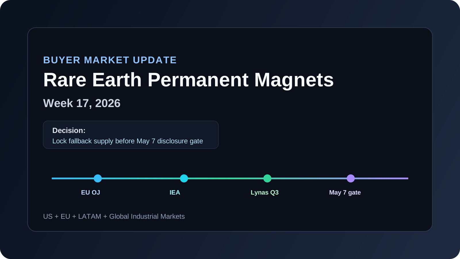
Rare Earth Permanent Magnets Market Update (2026-W17): New Quarter Data Tightens Buyer Allocation Planning
Week 17 rare earth permanent magnets update: verified NdFeB/SmCo supply and export-risk signals plus immediate sourcing actions for US, EU, and LATAM buyers.
Rare Earth Permanent Magnets Market Update (2026-W16): Buyer Hold Points Before Q2 Disclosures
April 2026 buyer update on NdFeB and Sm: verified 30-day changes, unresolved risks, and sourcing actions for US, EU, and LATAM teams before Q2 disclosures.
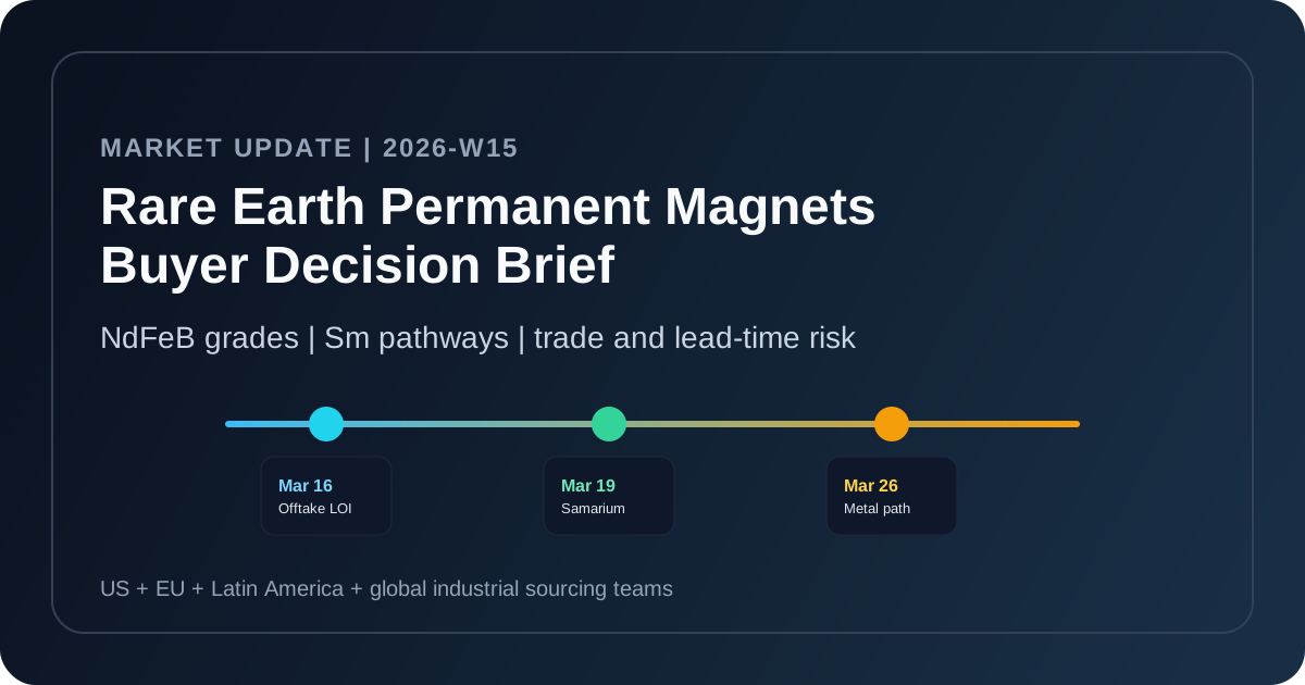
Rare Earth Permanent Magnets Market Update (2026-W15): Procurement Signals Buyers Should Act On Now
A buyer-focused March-April 2026 update on NdFeB grades, Sm-containing supply, trade-policy signals, and practical sourcing actions for US, EU, Latin America, and global industrial teams.