

Post-Assembly Magnetization for PM Rotors: Saturation Field Physics, Fixturing Stresses, and Sourcing Reality for EV Powertrains & Motor Engineers
Compare post-assembly magnetization for PM rotors: saturation evidence, sleeve shielding, fixture loads, and sourcing trade-offs. Request a drawing review.
Published and editorially reviewed: November 05, 2026. This global sourcing guide is for EV powertrain engineers, industrial motor designers, and procurement teams evaluating sintered NdFeB and SmCo permanent magnet rotor assemblies.
Post-assembly magnetization (PAM) means installing unmagnetized magnets into a rotor, then applying a magnetizing field to the assembly. It reduces magnetic attraction during insertion and bonding. It also moves the qualification challenge into the magnetizing fixture: can the required field reach every segment in the intended direction without damaging the rotor or tooling?
Choose PAM when the assembly benefit outweighs the cost of qualifying a rotor-specific pulse process. Before selecting equipment or a turnkey supplier, require three things: a material-specific magnetizing requirement, an analysis of field penetration through the actual rotor, and measured acceptance criteria correlated with motor performance. A large capacitor bank or a high open-bore field rating alone establishes none of these.
This article combines transparent screening calculations, a manufacturing-route comparison, and an RFQ checklist. It is an engineering synthesis, not a report of Ganzhou Magnets production trials. Numerical examples use stated assumptions; they are neither equipment settings nor supplier capability guarantees.
For a project discussion, submit your rotor drawing and acceptance requirements. Include the sleeve, magnet orientation, operating temperature, and planned production volume.
Scope, Assumptions, and Engineering Boundaries
- Applications: Interior permanent magnet (IPM) rotors with embedded segments and surface permanent magnet (SPM) rotors with retaining sleeves. A process qualified for one geometry does not automatically transfer to another.
- Materials: Sintered NdFeB, including high-coercivity and grain boundary diffusion (GBD) variants, and Sm2Co17. Obtain the exact supplier's magnetic data rather than treating grade names as complete specifications.
- Equipment: Capacitor-discharge magnetizers with purpose-designed external fixtures. Magnetization through the motor stator is a separate design route requiring its own electrical, thermal, and mechanical qualification.
- Model limits: The calculations below are screening estimates. Nonlinear iron properties, three-dimensional end effects, local magnetizing direction, and conductive loops can require transient finite element analysis (FEA).
- Release limits: Surface field mapping and back-EMF are useful acceptance measurements, but neither proves complete magnetization at every internal point. Establish their relationship to a qualified reference process before using them for release.

Figure 1: Conceptual external multipole fixture and sourcing comparison. The diagram is not to scale and contains no production capability certification.
1. The Pre-Magnetized Assembly Bottleneck
1.1 Mechanical Forces and Tile Chipping
Pre-magnetized segments attract steel tooling and rotor laminations, and can rotate or snap into place if unconstrained. Sintered rare-earth magnets are brittle metallic materials; impacts can chip their edges, damage coatings, or disturb a bondline. The actual insertion force depends on geometry, gap, neighboring magnets, and the magnetic return path.
For an approximately uniform field normal to a pole face, a useful magnetic-pressure screening estimate is:
F ≈ B_gap² × A / (2 × μ₀)
μ₀ ≈ 4π × 10⁻⁷ H/m
Here B_gap is the assumed flux density in the gap, not the catalog remanence, and A is the effective face area. With an assumed area of 50 mm × 120 mm = 0.006 m² and a uniform 0.6 T gap field:
F ≈ (0.6² × 0.006) / (2 × 4π × 10⁻⁷)
  = 0.00216 / 0.000002513
  ≈ 859 N
This hypothetical result explains why restrained insertion matters. It does not establish the load on a particular robot gripper. The expression contains no universal inverse-square law for gap dependence, and forces on multiple poles cannot simply be added as a net rotor load. Use the insertion trajectory and magnetic geometry to size tooling, then validate the result.
1.2 Ferrous Contamination and Bondline Control
Magnetized parts collect ferrous debris that can remain trapped around sleeves, adhesives, or bearing interfaces. Control machining swarf, inspect cleaned parts, and protect completed assemblies. A cleanroom classification is not automatically required for every rotor; specify cleanliness according to the motor air gap, insulation system, and failure analysis.
PAM makes insertion easier because the magnets have no deliberately established working magnetization during assembly. It does not eliminate dimensional inspection, debris control, adhesive process qualification, or safe handling after the pulse. Sleeving and adhesive cure temperatures must still respect material and coating limits even before magnetization.
1.3 A Practical PAM Process Sequence
A candidate sequence is incoming magnet inspection, orientation-controlled insertion, adhesive cure, sleeve installation, magnetization, magnetic inspection, balancing, and protected packing. Engineers should agree on the sequence before releasing the drawing: a sleeve may affect field penetration, while any subsequent mechanical operation may change balance or introduce contamination.
Anisotropic magnets retain their manufacturing easy-axis orientation even when unmagnetized. Installing a segment in the wrong orientation cannot be repaired merely by increasing pulse energy. Include orientation marks or a mistake-proof loading method in the assembly plan.
2. Saturation Field Physics: Specify Evidence, Not a Universal Multiplier
2.1 What the Magnetizing Requirement Must Describe
Intrinsic coercivity Hcj describes resistance to reversal on a defined hysteresis curve. It is not itself a universal specification for the field needed to magnetize an initially unmagnetized part. Required field depends on material processing, starting magnetic state, temperature, pulse duration, and field direction relative to the easy axis. High-coercivity or GBD grades therefore need supplier-specific qualification, rather than an assumed rule that every magnet needs exactly three times Hcj.
The material requirement should identify a validated magnetizing field and exposure condition. The fixture analysis should then show the local field component along the intended magnetization axis throughout each segment, including weak regions near bridges, ends, and leakage paths. Compare the time history with the supplier's requirement; an open-bore measurement is not a substitute for this loaded-field assessment.
Keep field strength and flux density distinct:
H: field strength in A/m or kA/m
B: flux density in tesla (T)
1 kOe ≈ 79.577 kA/m
μ₀ × 1 kOe ≈ 0.1 T
B = μ₀ × (H + M) inside a magnetic material
Equipment specifications sometimes express excitation as μ₀H in tesla. Label that convention explicitly; it is not the same as the local B inside a permanent magnet. For example, 20 kOe is about 1.59 MA/m and corresponds to μ₀H ≈ 2 T. Multiplying that field strength by three would give μ₀H ≈ 6 T, not 3 T. This is a unit-conversion example, not a recommended magnetizing threshold.
2.2 What Incomplete Magnetization Can Change
Incomplete or incorrectly directed magnetization can reduce useful flux linkage and alter pole balance, harmonics, and motor performance. The magnitude is geometry-specific. There is no defensible universal torque deficit, remanence loss, or temperature penalty that can be assigned to every partially magnetized rotor.
Ask the magnet supplier for initial magnetization or pulse-response data, relevant temperature conditions, and a reference measurement method. Ask the fixture supplier how its loaded field prediction was correlated with prototype measurements. These are separate responsibilities that should be connected in the process qualification record.
Published PAM research covers particular systems rather than a universal field recipe. Relevant examples include Tu et al.'s 160-kW IPM magnetization system and Choi et al.'s nonlinear magnetic equivalent circuit analysis. Their geometry and assumptions must be reviewed before transferring results to a new rotor.
3. Grade-Specific Qualification Matrix
Use this matrix to decide what evidence belongs in the RFQ. It deliberately avoids assigning unsupported saturation fields or pulse widths from a grade label. The exact grade datasheet and rotor process must supply those values.
| Material option | Why it enters the shortlist | Material evidence to request | PAM qualification focus |
|---|---|---|---|
| N35 | Candidate for moderate-flux designs | Supplier remanence, coercivity, dimensions, and temperature curves | Demonstrate field coverage and required flux after assembly. |
| N45 | Candidate where greater remanence is useful | Exact grade datasheet and magnetizing response | Check the loaded fixture field and leakage paths rather than reusing an N35 recipe. |
| N52 | Candidate for compact, high-flux designs | Temperature-dependent demagnetization curves and magnetizing data | Verify operating demagnetization margin separately from initial magnetization. |
| N42SH | Candidate for a higher-coercivity NdFeB design | Supplier-defined SH properties and pulse-response evidence | Qualify field direction and exposure through the actual IPM bridges or sleeve. |
| N45UH with GBD | Candidate where coercivity and rare-earth usage are design drivers | Diffusion process identification, section thickness, and magnetic data | Validate the actual diffusion variant; nominal grade equivalence does not establish an identical recipe. |
| N38EH with GBD | Candidate for more demanding temperature conditions | Operating-temperature curves and material-specific magnetizing requirement | Check fixture capability, thermal budget, and the qualified reference rotor. |
| Sm2Co17 30M | Candidate when SmCo temperature behavior is useful | Supplier definition of 30M, magnetic curves, coating and handling requirements | Qualify the specific SmCo material and retain controls for brittle segments. |
A grade suffix is not an operating-temperature approval for the assembled motor. The load line, temperature exposure, opposing field, and structural design still need evaluation. Use the neodymium magnet product overview as a starting point for material discussions, then request the exact supplier data.
4. Transient Eddy-Current Shielding: The Sleeve Barrier
4.1 Pulse Shape and Screening Time Scales
A capacitor bank stores E = ½CV². For an ideal weakly damped RLC discharge, a characteristic first half-cycle is approximately π√(LC); real waveform shape depends on resistance, damping, switching, and the loaded fixture. Specify measured rise time, peak current, pulse duration, and any reverse-current tail instead of calling every pulse a fixed number of milliseconds.
Conductive sleeves, end rings, shafts, and magnet segments can support eddy currents that oppose a changing field. As one limited screening model, diffusion across a planar nonmagnetic conducting wall has a characteristic scale:
τ_diff ~ μ × σ × d²For an illustrative wall thickness d = 0.0015 m, assumed conductivity σ = 0.80 × 10⁶ S/m, and permeability μ = μ₀:
τ_diff ~ (4π × 10⁻⁷) × (0.80 × 10⁶) × (0.0015)²
       ≈ 2.26 × 10⁻⁶ s = 2.26 microseconds
This is a time scale, not an attenuation percentage. A separate thin, long conducting-cylinder estimate for a uniform axial field is τ ~ μ₀σrd/2. With assumed titanium conductivity 0.58 × 10⁶ S/m, radius 0.04 m, and wall 0.0012 m, it gives about 17.5 microseconds, or 0.0175 ms. That axial model does not describe an external multipole radial fixture.
Neither calculation establishes a mandatory 15–25 ms pulse. Use the actual pulse spectrum, current paths, sleeve properties, end geometry, and magnet arrangement to determine whether shielding is significant. Transient electromagnetic analysis and measured prototype response should resolve the uncertainty; do not infer a fixed energy surcharge from the sleeve material name.
4.2 Material and Construction Trade-Offs
Metal sleeves require their actual conductivity, permeability, thickness, and joint details in the model. Slots or segmentation can interrupt some current paths, but may also affect mechanical retention. A continuous copper or aluminum component can increase shielding relative to a more resistive alloy; this is a design issue to evaluate rather than proof that PAM is impossible.
Carbon-fiber composites are electrically anisotropic. Conductive fibers, fiber direction, layup, and contacts can permit current paths, so a CFRP sleeve must not be modeled automatically as an insulator with zero eddy-current shielding. Ask for relevant directional properties and check the assembly rather than only the resin's conductivity.
Changing capacitance or inductance changes pulse shape as well as equipment loading. A longer pulse can improve penetration in some designs while increasing losses or changing peak field. Treat pulse optimization as a coupled electromagnetic and thermal task.
5. Lorentz Forces and Thermal Shocks: Fixture Survivability
5.1 Convert Force into Stress with the Actual Geometry
For a straight conductor perpendicular to a local field, the force per unit length is approximately:
f = I × B
At I = 25,000 A and B = 4 T:
f ≈ 100,000 N/m
This hypothetical result is a line load, not a fixture pressure in MPa. Stress depends on conductor cross-section, winding arrangement, support spans, preload, insulation, and containment. A fixture design review should connect the electromagnetic force distribution to structural analysis and a defined fatigue duty.
Specify shot rate, expected service life, cooling conditions, inspection intervals, and replacement responsibility. Ask the supplier how conductor movement, insulation wear, electrical resistance changes, and cooling leaks are monitored. Vacuum impregnation or reinforcement can be useful design choices, but the manufacturing method alone does not certify fixture life.
5.2 Heating and Adhesive Integrity
Resistive loss in a modeled circuit is E_loss = ∫i(t)²R(t)dt; additional losses occur in conductive rotor parts. Estimating component temperature rise requires the energy deposited in that component and its heat capacity, with attention to local hot spots. Total bank energy cannot be converted directly into a universal rotor temperature rise.
Qualify the adhesive cure state before pulsing and set project-specific limits for the magnet, coating, sleeve, bondline, and fixture. Record both individual-shot heating and accumulated temperature at the intended production rate. A process that works on one cold prototype may fail when repeated on a warm fixture.
Shen et al.'s induction-assisted PAM paper is relevant literature for evaluating a heating-assisted route. It is not evidence that a particular temperature excursion is acceptable for your adhesives or that any supplier offers that process.
6. Manufacturing Route Comparison: In-House vs. Turnkey Sourcing
Compare the routes using the same rotor drawing, release tests, accepted-unit demand, and ownership period. Generic equipment prices, scrap percentages, and annual-volume breakpoints can obscure the actual decision.
| Evaluation dimension | Route A: Pre-magnetized tile assembly | Route B: In-house PAM | Route C: Turnkey rotor sourcing |
|---|---|---|---|
| Equipment and tooling | Restrained insertion and orientation tooling | Qualified magnetizer, fixture, cooling, handling, and inspection | Supplier equipment cost may enter unit price or separately quoted tooling. |
| Assembly yield | Track chips, coating damage, placement, and bondline defects. | Track those defects plus pulse-process rejects. | Agree supplier yield responsibility, rejection handling, and delivered acceptance. |
| Contamination | Protect magnetized segments throughout assembly. | Maintain cleanliness before and after magnetization. | Require cleanliness and packaging evidence plus receiving controls. |
| Cycle time | Depends on insertion method and restraint. | Include loading, charging, cooling, measurement, and unloading. | Include supplier capacity, freight, buffer stock, and receiving inspection. |
| Magnetic assurance | Verify incoming magnets and assembled rotor performance. | Qualify loaded-field coverage and monitor the validated process. | Require traceable release records and access to qualification evidence. |
| Balancing | Plan correction access around magnetized parts. | Define balancing relative to sleeving and magnetization. | Specify final assembly state and contractual balance limits. |
| Handling and safety | Magnetic attraction and fragment controls are needed. | Adds high-voltage discharge and fixture-containment requirements. | Delivered magnetized rotors still require magnetic handling controls. |
| Commercial exposure | Buyer owns assembly process and inventory. | Buyer owns equipment utilization, maintenance, and process development. | Buyer retains supplier, logistics, quality, and change-control exposure. |
For a transparent cost screen, divide annual fixed process cost by accepted annual output, then add variable conversion cost, measured yield losses, inspection, logistics, and warranty provisions. Compare it with a supplier quote that states exactly which operations and tests are included.
Illustrative arithmetic only: if annualized fixed costs are $60,000 and output is 20,000 accepted rotors, fixed cost is $3 per accepted rotor. At 5,000 accepted rotors, it is $12. These assumed figures demonstrate utilization sensitivity; they are not market quotations or Ganzhou Magnets pricing. Include financing, fixture replacements, commissioning, and downtime in a real comparison.
Before requesting prices, send the same drawing and test scope for a sourcing review. This makes bids comparable and exposes excluded tooling or inspections early.
7. Quality Assurance: Detecting Incomplete Magnetization
7.1 Why One Surface Reading Is Insufficient
A Hall probe measures the field at a specified location and orientation. A single reading cannot resolve the magnetization distribution inside an IPM rotor, and the measured surface field is not the material's remanence Br. Probe stand-off, sleeve thickness, rotor position, and temperature also affect the result.
A circumferential scan reveals pole shape, symmetry, zero crossings, and harmonics. Open-circuit back-EMF in a defined stator reveals linked flux at a defined speed. These complementary measurements improve defect detection, but a good integrated result can conceal local deficiencies. Avoid claiming that agreement with FEA mathematically proves saturation throughout the magnet volume.
7.2 A Qualification and Production Test Plan
First, qualify representative prototypes with modeled field coverage, supplier material data, measured pulse waveforms, and reference magnetic tests. A controlled excitation-stepping study can show when useful flux stops increasing significantly. Define repeatability, measurement uncertainty, temperature control, maximum permitted excitation, and plateau acceptance before the test. An arbitrary voltage increment and a small flux change are not universal proof of saturation.
Second, establish production measurements correlated with qualified reference assemblies. Specify probe path and stand-off, sampling positions, test temperature, speed, stator identity, voltage definition, and harmonic calculation. Surface-flux THD and back-EMF THD are different measurands; limits must follow the motor requirements rather than a generic percentage.
For a sinusoidal fundamental and a stated line-to-line RMS convention, the peak phase flux linkage can be estimated as:
ω_e = p × 2π × n / 60
ψ_pm,peak = √(2/3) × E_LL,rms,fund / ω_e
Here p is the number of pole pairs and n is mechanical speed in rpm. The relation assumes balanced sinusoidal phase fundamentals; it does not apply unchanged to arbitrary waveform RMS values or other flux-linkage conventions. Match the definition to the motor model and test instrumentation.
Third, define reaction rules for excursions: hold affected assemblies, check waveform and fixture condition, investigate material or assembly changes, and requalify when the change affects the validated process. Retain traceability from magnet lot and drawing revision through the release report.
8. Engineering & Procurement RFQ Checklist
- Material and orientation: Exact supplier grade, magnetic data at relevant temperatures, magnet geometry, coating, easy-axis direction, and starting magnetic state. Request material-specific magnetizing data instead of imposing a universal coercivity multiplier.
- Complete rotor geometry: Lamination grade and thickness, bridges, shaft, sleeve dimensions, sleeve conductivity or composite layup, end rings, and conductive contacts. Identify which components are present during pulsing.
- Adhesive and thermal boundaries: Cure schedule and verification method, permissible pulse exposure, component temperature limits, and the measurement method for representative hot spots.
- Pulse and fixture qualification: Loaded-field analysis, waveform records, pulse polarity and reverse-tail control, production repetition rate, fixture maintenance, and qualification responsibility. Agree the evidence required before ordering production equipment.
- Magnetic acceptance: Hall-map path, back-EMF test stator and speed, voltage and harmonic definitions, tolerances, measurement uncertainty, sampling plan, and lot-level traceability. State which measurements are performed on every unit.
- Mechanical release: Final assembly configuration, runout, retention, balance tolerance, correction locations, and sequence. Where ISO 21940-11 applies to rigid-rotor balancing, specify the required grade and service conditions; a grade label alone does not validate overspeed retention or flexible-rotor behavior.
- Commercial and shipping scope: Tooling ownership, capacity, accepted yield basis, lead time, change control, inspection records, warranty, magnetic shielding, and receiving checks. Agree transport requirements with the carrier for the packed assembly and intended route; packaging does not eliminate magnetic hazards.
9. Frequently Asked Questions
Can a motor's own stator windings perform post-assembly magnetization?
Potentially, if the motor and magnetization process are designed for it. Check available ampere-turns, local field coverage, winding temperature, insulation stress, mechanical forces, switching, and the resulting magnetic state. Ordinary motor operating ratings do not establish pulse-magnetization suitability. Compare a validated stator-based proposal with an external fixture rather than treating either route as universally required or prohibited.
Can one pulse disturb adjacent poles?
Yes. Field direction, return paths, leakage, and an unwanted reverse-current tail can affect neighboring segments. A multipole fixture needs the intended spatial field pattern, alignment to rotor pole positions, and controlled waveform polarity. Qualify the complete pole pattern and phase relationship; a peak current reading alone cannot detect a wrongly oriented pole.
How can we check deep IPM magnets?
Combine a validated local-field model with material response data, controlled prototype excitation studies, and reference measurements correlated with the motor's performance. Surface scans and back-EMF are useful checks but do not uniquely reconstruct internal magnetization. Escalate unresolved regions to a magnetic specialist and additional sample investigation before accepting the production recipe.
Are Halbach arrays suitable for PAM?
They can be challenging because neighboring segments need different magnetization directions and may be difficult to reach with one fixture. Feasibility depends on segmentation, easy-axis orientation, geometry, and fixture design; there is no justified universal percentage of applications that must use pre-magnetized segments. Compare both assembly routes using the Halbach array fixturing and sourcing guide.
Does titanium always need more pulse energy than carbon fiber?
No fixed energy uplift follows from those material names. Titanium geometry and conductivity matter, while CFRP has directional conductivity that depends on construction. Compare the loaded field and losses for the actual sleeve and waveform. A pulse-width change also changes circuit loading, so validate the complete recipe rather than adding a generic percentage to bank energy.
When should an OEM buy a turnkey rotor?
Consider turnkey sourcing when a qualified supplier can meet the drawing and traceable acceptance plan more economically than maintaining the process internally. High product mix, limited fixture utilization, and scarce magnetics staff can favor outsourcing. Stable volume and existing process capability can favor in-house PAM. Use accepted-unit cost and qualification evidence; annual volume alone cannot establish the answer.
Request a PM Rotor Sourcing and Magnetization Review
Send Ganzhou Magnets your rotor drawing, magnet grade, sleeve construction, operating conditions, annual volume, and magnetic acceptance plan. Ask for written confirmation of feasible scope, qualification evidence, inspection coverage, tooling costs, and lead time before selecting a supply route.
Sources & References
The following three IEEE papers provide relevant research routes. DOI bibliographic records were checked on November 05, 2026. The calculations and procurement framework above are explicitly stated engineering syntheses; these citations do not establish supplier equipment capability, commercial prices, or universal production thresholds.
- Tu, Z., et al. (2024) — Design and Experiment of Post-Assembly Magnetization System for a 160-kW Interior Permanent-Magnet Motor. IEEE Transactions on Applied Superconductivity, 34(5), pp. 1–7. Relevant to qualifying a defined IPM magnetization system; do not transfer its settings without reviewing its design conditions.
- Shen, J.-X., et al. (2026) — Post-Assembly Magnetization With Induction Heating for Large-Scale Permanent Magnet Electrical Machines. IEEE Transactions on Magnetics, 62(7), article 8101307. A research reference for induction-assisted PAM, not an adhesive-temperature allowance or a general fixture-life specification.
- Choi, Y.-T., et al. (2026) — Modeling and Prediction of Post-Assembly Magnetization Characteristics in IPMSM Based on Nonlinear MEC Analysis. IEEE Transactions on Magnetics, 62(10), article 7002405. Relevant to nonlinear magnetic equivalent circuit modeling; model applicability must be assessed for the proposed topology.
Review boundaries: Published and editorially reviewed November 05, 2026. No first-party production dataset or independently audited factory capability is claimed. Review by November 2027, or sooner if material data, rotor geometry, acceptance criteria, or the applicable standards change. Release requires a project-approved qualification and inspection plan; this guide does not replace one.
Author

Categories
More Posts
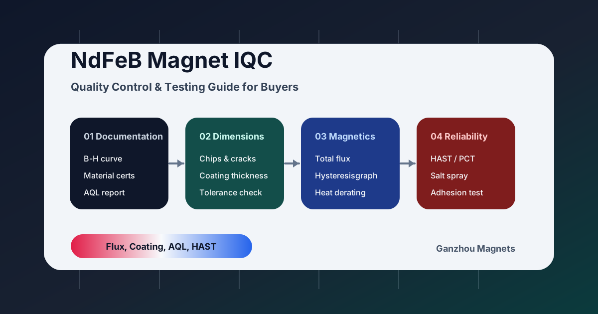
Neodymium Magnet Quality Control & Testing: The Complete IQC Guide for Buyers
A comprehensive guide to Incoming Quality Control (IQC) for NdFeB magnets. Learn how to test magnetic flux, verify coatings with HAST/SST, and audit Chinese suppliers.
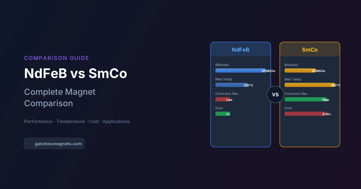
NdFeB vs SmCo: Guía completa de comparación de imanes para ingenieros
Comparación detallada de imanes de neodimio (NdFeB) y samario-cobalto (SmCo) que cubre rendimiento magnético, estabilidad térmica, resistencia a la corrosión, costo y recomendaciones por aplicación.

Reducing Heavy Rare Earth Costs: The 2026 Buyer's Guide to Grain Boundary Diffusion (GBD) NdFeB Magnets
A comprehensive guide for engineers and procurement teams on using Grain Boundary Diffusion (GBD) to reduce Dysprosium (Dy) and Terbium (Tb) costs in high-temperature NdFeB magnets.