
Halbach Array Magnet Assemblies: Engineering Principles, Sourcing Tolerances, and Fixturing Guide for Industrial Buyers
Source Halbach array magnet assemblies: compare sourcing tolerances, fixturing, inspection, and rotor retention. Request a drawing review from Ganzhou Magnets.
Published and editorially reviewed: October 29, 2026. Written for electromechanical engineers, motor designers, linear stage developers, precision automation architects, and B2B procurement managers sourcing sintered NdFeB and SmCo permanent magnet assemblies.
Halbach array magnet assemblies rotate the magnetization direction between neighboring segments to concentrate flux toward a selected working region and reduce the field on the other side. For linear stages, slotless motors, and field-generation systems, this can reduce the need for a magnetic return yoke. The benefit depends on geometry, segmentation, air gap, and the comparison design; there is no universal flux-gain multiplier.
Procuring a Halbach array differs from buying loose permanent magnets. Segments can attract, repel, or rotate during insertion, so the assembly sequence needs constrained tooling. Buyers also need a magnetization-vector drawing, temperature-dependent material data, and a field-map acceptance plan. These requirements connect electromagnetic performance to tolerances, bonding, and inspection.
This guide provides electromechanical engineers and procurement directors with the physics, tolerance budgets, fixturing mechanics, and sourcing specifications needed to transition Halbach assemblies from prototype to serial production. For custom assembly inquiries, request an engineering drawing review.
Scope, Assumptions, and Use Case Boundaries
- Materials: High-energy sintered Neodymium-Iron-Boron (NdFeB) and Samarium-Cobalt (SmCo 2:17). Bonded isotropic magnets magnetized via multi-pole impulse fixtures are treated as a lower-flux alternative.
- Topologies Covered: Planar linear Halbach arrays (used in linear motors, maglev tracks, and planar multi-axis stages) and cylindrical Halbach arrays / Halbach cylinders (used in high-speed rotary motor rotors, magnetic couplings, and beam steering quadrupoles).
- Analytical assumptions: The planar field model assumes an infinitely long and wide, periodic array, relative permeability near one, uniform remanence, equal segment widths, negligible gaps, and no adjacent iron. It estimates the fundamental field amplitude, not a complete motor or cylinder.
- Manufacturing boundaries: Finite-length leakage, magnetic saturation, assembly loads, thermal expansion, demagnetization, and rotor containment require application-specific analysis and prototype qualification. Numerical drawing values below are discussion examples, not universal acceptance limits.
- Evidence and audience: This global, English-language buyer guide combines cited engineering literature with reproducible calculations and an RFQ framework. It does not report factory measurements, customer outcomes, certified supplier capabilities, or country-specific compliance approval.
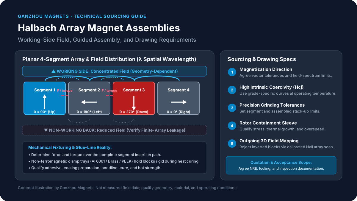
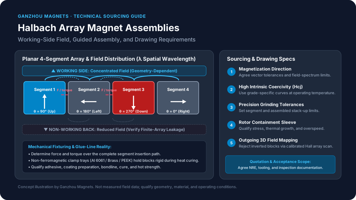
Figure 1: Schematic cross-section of a 4-segment-per-wavelength planar Halbach array. Spatial rotation of magnetization vectors yields constructive interference on the working face and destructive cancellation on the non-working back face. Use constrained, suitably nonmagnetic tooling for assembly; force magnitude and direction depend on the insertion path.
1. The Physics of the Halbach Effect: One-Sided Field Augmentation
The Governing Principle of Spatial Vector Rotation
A Halbach pattern rotates the magnetization vector spatially rather than simply alternating normal north and south poles. Halbach's multipole paper provides the foundational rare-earth magnet treatment; Zhu and Howe's machine review discusses applications and design trade-offs.
For the planar illustration, measure angle counterclockwise from +x, with +y toward the working face:
θ_m(x) = π/2 + kx, k = 2π/λHere λ is one full 360° magnetization cycle, equal to two pole pitches. Four segments per wavelength therefore means two segments per pole. Reversing the rotation sense exchanges the concentrated-field and reduced-field sides. Cylinders require a topology-specific angular pattern; segment count alone does not define pole count or field direction.
Discrete Segment Approximation and the Segmentation Factor (k_d)
Conventional uniaxially pressed sintered blocks have a preferred magnetic orientation. Manufacturers approximate spatial rotation by assembling separate blocks with specified magnetization directions.
For a Halbach array discretized into M magnet segments per spatial wavelength λ (or M/2 segments per pole), the theoretical fundamental peak normal-field amplitude B_y,peak(y) at a distance y above the working face is governed by:
B_y,peak(y) = B_r · k_d · (1 - e^(-k d)) · e^(-k y)Where:
B_ris the remanence (residual flux density) of the magnet alloy (in Tesla).k = 2π / λis the spatial wavenumber.dis the thickness (height) of the magnet blocks along they-axis.yis the physical air-gap distance from the magnet surface to the target surface.k_dis the discrete segmentation factor:
k_d = sin(π / M) / (π / M)Evaluating this segmentation factor reveals the engineering and economic trade-off of segment count:
M = 4segments per wavelength (2 segments per pole, 90° rotation):k_d = sin(π/4) / (π/4) = (√2/2)/(π/4) ≈ 0.9003(achieves 90.0% of the theoretical continuous flux limit).M = 8segments per wavelength (4 segments per pole, 45° rotation):k_d = sin(π/8) / (π/8) ≈ 0.9745(achieves 97.4% of the continuous limit).M = 16segments per wavelength (8 segments per pole, 22.5° rotation):k_d = sin(π/16) / (π/16) ≈ 0.9936(achieves 99.4% of the continuous limit).
The Engineering Law of Diminishing Returns
Within this ideal fundamental model, moving from four to eight segments per wavelength increases the field amplitude by about 8.2% at unchanged remanence, wavelength, thickness, and gap. More segments also change the harmonic spectrum, but do not guarantee a particular THD, torque ripple, or cogging torque. Trumper and colleagues analyze planar arrays for synchronous machines.
Reproducible screening example, not measured performance: With B_r = 1.30 T, λ = 40 mm, d = 10 mm, and y = 2 mm, the formula gives approximately 0.677 T for M = 4 and 0.733 T for M = 8. Use consistent length units in kd and ky. Finite width, end effects, glue gaps, and nearby iron can change both values.
Start with four segments when assembly simplicity matters, then compare eight segments against the actual field-spectrum requirement. More parts mean more joints and tolerance contributors; the effect on yield must come from the proposed process, not an assumed scrap multiplier.
2. The Hidden Fixturing Hazards: Managing Inter-Segment Repulsion
Assembly forces depend on magnet geometry, spacing, magnetization direction, and the insertion path. Adjacent segments can attract, repel, and exert overturning moments. Plan the full insertion sequence, including the load on each temporary clamp.
A Force Scale Is Not a Fixture Rating
A magnetic stress scale is p* = B² / (2μ₀). Using an assumed local field of 1.44 T gives p* ≈ 825 kPa; multiplying by an illustrative 50 × 20 mm area gives 825 N. This arithmetic is not a prediction of lateral insertion force: remanence is not the local gap field, and a real force calculation must integrate the Maxwell stress tensor over a suitable surface or use validated force measurements.
Do not size clamps from that scalar example. Determine force and torque over the full insertion path, include a justified design margin, and qualify the tooling with controlled trials. Brittle sintered magnets need protection from impact, edge loading, and uncontrolled rotation.
Progressive Non-Magnetic Assembly Fixturing
A practical assembly plan should include:
- Tooling material: Select stiff, suitably nonmagnetic guides such as aluminum or qualified engineering polymers. Verify the magnetic response of stainless parts after machining; a nominal austenitic grade does not ensure negligible attraction in every condition.
- Guided insertion: Restrain unwanted translation, rotation, and lifting while a lead screw or guided actuator controls the intended motion. Design catches and stops for loss of actuator pressure.
- Progressive locking: Retain installed segments through the complete cure and handling sequence. Check removal of temporary tooling without disturbing the bonded array.
Structural Adhesive Selection and Bondline Mechanics
Qualify the adhesive on the actual magnet coating and carrier finish, using the intended surface preparation and cure schedule. Room-temperature lap-shear data alone do not establish hot creep resistance, fatigue life, peel strength, or suitability for vacuum use.
- Temperature: Obtain current manufacturer data for service temperature, glass transition, hot strength, and long-term creep. A product name or a high nominal
T_gdoes not qualify the assembly. - Bondline: Treat
0.05–0.12 mmas an illustrative discussion range only. Agree a thickness, spacer method, surface preparation, and cure process through joint tests; adding glass beads also requires process qualification. - Acceptance: Record resin batch, mix ratio, cure time/temperature, and representative coupon or assembly qualification results. Include thermal cycling and the relevant fluids or humidity exposure.
3. Local Demagnetization Risk: Why Halbach Arrays Demand High Coercivity (H_{cj})
Ambient temperature alone cannot select an NdFeB grade. Halbach segments experience different local magnetic operating points, and armature reaction or fault current can add opposing fields. Winter, Kral, and Schmidt specifically study temperature-related degradation in segmented Halbach arrays.
Check Local Operating Points, Not a Universal Field Threshold
B_r/μ₀ is a dimensional field scale, not a geometry-independent internal demagnetizing field. Comparing it directly with a room-temperature coercivity value cannot establish whether an assembly passes. Likewise, a single linear temperature coefficient cannot supply a reliable acceptance table at 100°C.
Ask for full normal and intrinsic demagnetization curves at the relevant magnet temperatures. Use the local field component opposing magnetization, including fault conditions, to check for irreversible loss around corners and segment boundaries. The material model, mesh, and temperature assumptions should accompany the result.
Six-Point Material Qualification Matrix
| RFQ input | Why it changes selection | Evidence to request |
|---|---|---|
| Continuous and peak magnet temperature | Ambient or coolant temperature may miss rotor hot spots | Thermal model and representative temperature measurements |
| Local opposing field | Segment corners and armature reaction can govern irreversible loss | FEA with the actual segmentation and worst-case current |
| Grade and minimum magnetic properties | Grade suffix alone is insufficient for acceptance | Supplier specification with minimum remanence and coercivity |
| Temperature-dependent demagnetization curves | The curve knee and operating point determine margin | Normal and intrinsic curves across the operating range |
| Grain boundary diffusion route, if proposed | Benefit depends on alloy, thickness, and process | Process-specific property data and batch traceability |
| Post-exposure field retention | A simulated margin needs physical confirmation | Agreed before/after field maps following thermal and fault qualification |
SH, UH, and EH grades can be candidates when greater coercivity is needed; none is universally mandatory or sufficient. GBD is an available processing route, not proof of a particular grade or guaranteed assembly performance.
4. Sourcing Tolerances and Harmonic Purity: What to Put on the 2D Drawing
Define magnetic and mechanical requirements together. A tighter segment tolerance is useful only when it controls a meaningful assembly or field error.
1. Magnetization Direction Angular Tolerance
Specify a coordinate system, a vector for every segment, and the measurement method. Values such as ±1.5°, or ±1.0° for a more demanding design, are RFQ examples, not standard requirements. Use sensitivity analysis to connect the tolerance to the field spectrum at the working gap. Angular error alone does not determine motor cogging torque; stator slotting and other geometry also matter.
2. Precision Dimensional Grinding Tolerances
For an illustrative straight stack, sixteen pieces each oversized by 0.05 mm add 0.80 mm in the worst case. A cylindrical assembly needs a separate stack analysis for sector angle, chord, carrier diameter, and bondlines; the straight-stack sum is not a cylinder closure calculation.
Discuss ground mating-face tolerances such as ±0.02–0.05 mm only after that analysis. Define final assembled pitch, bore or outside diameter, runout, and the temperature of dimensional inspection. Specify coating thickness and intended glue gaps rather than assuming bare-magnet contact.
3. Edge Chamfers and Corner Geometry
Agree edge breaks to limit chipping while preserving active material and bond area. A 0.20–0.40 mm × 45° chamfer may be a discussion starting point for sufficiently large blocks, but can be excessive on miniature segments. Define acceptable chips and coating defects with the supplier, then verify their effect on the working field.
5. High-Speed Halbach Rotors: Retention Sleeving and Dynamic Containment
For a rotating assembly, centrifugal loading, magnetic forces, interference pressure, thermal expansion, and overspeed conditions must be considered together. Circumferential speed is v = ωr; RPM alone does not establish sleeve suitability. There is no universal 50 m/s threshold that approves an unsleeved design or mandates one particular sleeve.
Sintered magnets are brittle, and adhesive strength can degrade with temperature and time. A rotor retention design needs material allowables, tolerances, stress/fatigue analysis, and application-appropriate overspeed qualification.
Containment Sleeve Material Selection Matrix
| Sleeve material | Potential benefit | Limitation to resolve before ordering |
|---|---|---|
| Carbon fiber reinforced polymer (CFRP) | High specific strength and a tailored hoop layup | Conductive fibers can still support eddy currents; verify layup-dependent losses, radial heat flow, resin temperature limit, and prestress |
| Titanium alloy | Strong metallic containment with relatively low conductivity | Check alloy condition, interference, fatigue, thermal growth, and electromagnetic loss |
| Nickel alloy, such as Inconel 718 | Candidate where strength and elevated temperature matter | Density and eddy-current heating can offset benefits; use certified material condition |
| Austenitic stainless steel | Accessible manufacturing route for some designs | Strength and magnetic response depend on grade and processing; verify heating and required wall thickness |
Carbon Fiber Sleeves: Qualification Questions
CFRP is an option for high-speed rotors, but is not an electrically insulating material by default. Neither a fiber-strength number nor an RPM claim qualifies a finished sleeve. Ask who owns the laminate design, cure control, interference/prestress calculation, and overspeed test. Model heat paths through the sleeve, shaft, and end structures rather than assuming all rotor heat can leave axially.
6. Build vs. Buy: Sourcing Loose Segments vs. Turnkey Assemblies
Choose loose segments when you have a qualified assembly process, appropriate tooling, and inspection capability. Compare a complete assembly quotation when those capabilities would need to be developed. Neither route is always cheaper.
Compare Cost per Accepted Assembly
Request line items for magnets, coating, fixtures, assembly labor, adhesive/cure, field inspection, qualification, packaging, and freight. Separate recurring costs from NRE and tooling ownership.
Cost per accepted unit = (recurring batch cost + allocated NRE) / accepted unitsUse supplier quotations and pilot-run yield data, not generic scrap rates. A damaged segment may require rework or assembly rejection depending on when it is found and the qualified repair process. A reversed segment distorts the field; pre-bond polarity checks and a final field map can identify the fault.
Agree Deliverables Before Ordering
- Assembly plan: Who designs the fixture, verifies vectors, and records the cure process?
- Retention and balance: Who owns the sleeve analysis and, for rotors, the balance specification at the relevant speed?
- Magnetic report: Agree coordinate axes, working and back-face scan paths, probe stand-off, sample spacing, calibration, field limits, and harmonic analysis window.
- Traceability: Link the supplied report to the assembly serial or batch number and document any outsourced steps.
To compare quotations for your design, ask Ganzhou Magnets to confirm the proposed assembly scope and the documentation available for it. This guide does not certify any particular production process or inspection capability.
7. Halbach Array Topologies & Engineering Trade-Off Matrix
Use this matrix to narrow the RFQ scope. The planar segmentation factor applies to the ideal planar fundamental model above; it must not be copied directly to cylinder field predictions.
| Configuration | Candidate use | Main trade-off | RFQ requirement |
|---|---|---|---|
| Four-segment planar wavelength | Linear drives and positioning tracks | k_d ≈ 0.9003; fewer parts but a different harmonic spectrum from finer segmentation | Define working gap, wavelength, end length, and field limits |
| Eight-segment planar wavelength | Stages requiring tighter field-spectrum control | k_d ≈ 0.9745; more pieces and joints | Compare measured harmonics and assembly cost at the same geometry |
| Internal-field dipole cylinder | Bore-field instruments or compatible machine geometries | Field uniformity depends on radius ratio, segmentation, and finite length | State bore region, vector pattern, uniformity metric, and assembly sequence |
| Internal-field multipole cylinder | Field-gradient systems or matching motor pole layouts | Pole count follows the magnetization pattern, not the number of arcs alone | Supply pole count, coordinate convention, and required field map |
| External-field Halbach rotor | Inner rotor with an external stator | Field is concentrated outside; containment adds effective magnetic gap | Define active outside diameter, sleeve envelope, temperature, and overspeed conditions |
| Monolithic magnetized ring alternative | Designs prioritizing fewer assembly joints | A conventional multipole ring is not automatically a Halbach pattern | Confirm achievable vector distribution, material orientation, field amplitude, and tooling quotation |
| SmCo-based segmented assembly | Applications where thermal stability merits evaluation | Brittle material; adhesive, carrier, and retention may set the temperature limit | Request grade-specific curves, mechanical qualification, and environment compatibility |
For material discussions, see the sintered NdFeB product overview; the assembly drawing and temperature-dependent data should govern final selection.
8. Halbach Array Sourcing & Drawing Specification Checklist
Use this checklist to make quotations and incoming inspection comparable:
- Vector drawing: Assign a segment identifier, magnetization vector, angle tolerance, and polarity-verification method in a shared coordinate system.
- Material and environment: Specify grade minimums, magnet temperature, peak current/fault cases, corrosion exposure, and evidence for demagnetization margin.
- Mechanical stack: Define segment and assembled dimensions, coating, chamfers, bondline, carrier datums, runout, and inspection temperature.
- Bond qualification: Agree coating preparation, adhesive/cure, bondline control, hot creep and thermal-cycle qualification, and allowable repair.
- Retention: For rotors, assign responsibility for stress, thermal growth, balance, overspeed conditions, and sleeve validation.
- Field acceptance: Define stand-off, scan region, axes, spatial resolution, calibration uncertainty, working-field amplitude/uniformity, and allowed back-face leakage. For THD, define the fundamental, harmonic range, and analysis window; a numerical limit without this method is ambiguous.
- Commercial handoff: Record NRE ownership, pilot quantity, sample approval, lead time, inspection records, packaging restraints, and change-control requirements.
9. Frequently Asked Questions (FAQ)
Q1: Why can't I just buy loose magnet blocks and glue a Halbach array together on our bench?
Loose-segment sourcing can work when the buyer has qualified tooling, trained operators, and a polarity/field inspection process. Do not infer handling forces from grade alone. Segment dimensions, geometry, and the insertion path determine the force and torque; unconstrained assembly can damage magnets and injure operators.
Q2: Does a Halbach array really eliminate 100% of the magnetic field on the back side?
An ideal continuous, infinitely extended planar array can have zero field on one side. Real finite, segmented assemblies have leakage from ends, gaps, and vector errors. There is no universal 95–98% reduction guarantee. Specify back-face field at a defined distance and scan region; eliminating a return yoke also requires mechanical and electromagnetic design checks.
Q3: How do you verify that none of the segments were installed backwards?
Check each segment's polarity/vector before bonding, using a documented reference orientation and appropriate magnetic measurement. After assembly, compare a calibrated multi-axis field scan with the approved reference map. Choose stand-off and sample spacing to resolve individual segment errors; neither visual coating inspection nor a single peak-gauss reading is sufficient.
Q4: When should an engineer choose an 8-segment array over a 4-segment array?
Compare both at the same wavelength, thickness, gap, and material. The ideal fundamental factor rises from about 0.9003 to 0.9745, an 8.2% relative increase. Choose eight only when its field spectrum or amplitude benefit justifies more segments and joints. Motor torque ripple and cogging still require analysis of the complete machine.
Q5: Can Halbach arrays be made from Samarium-Cobalt (SmCo) instead of NdFeB?
Yes. Evaluate SmCo when its grade-specific magnetic properties and temperature stability suit the application. Maximum service temperature belongs to the complete assembly: adhesive, coatings, retention, and carrier may impose a lower limit than the magnet. Radiation, vacuum, or corrosive service requires separate qualification; SmCo is not automatically immune or approved.
Q6: How do thermal expansion mismatches between NdFeB segments and aluminum or steel carriers affect array lifetime?
NdFeB expansion is direction-dependent, and the vector rotates between segments. Differential expansion relative to a carrier changes joint shear, peel stress, and rotor interference. Obtain material coefficients and adhesive properties for the actual temperature range, analyze the joint, and test representative thermal cycles. A more compliant bondline or a different carrier can help, but neither follows from a universal minimum glue thickness. Low-expansion alloys such as Invar can also be ferromagnetic, so assess their effect on the field before selecting them.
Request a Halbach Array Engineering & Sourcing Review
Transitioning a Halbach array from simulation to serial manufacturing? Send Ganzhou Magnets your 2D drawings, 3D STEP models, target air-gap flux density, operating thermal envelope, and containment sleeve requirements. Ask us to confirm manufacturing feasibility, quotation scope, tooling responsibility, and available inspection documentation for your design.
Sources & References
- Halbach, K. (1980) — Design of permanent multipole magnets with oriented rare earth cobalt material. Nuclear Instruments and Methods, 169(1), 1–10. Foundation for oriented rare-earth multipole magnet structures; not a manufacturing tolerance specification.
- Zhu, Z. Q., & Howe, D. (2001) — Halbach permanent magnet machines and applications: a review. IEE Proceedings - Electric Power Applications, 148(4), 299–308. Background on machine configurations and electromagnetic design trade-offs.
- Trumper, D. L., Williams, M. E., & Nguyen, T. H. (1993) — Magnet arrays for synchronous machines. Conference Record of the 1993 IEEE Industry Applications Conference Twenty-Eighth IAS Annual Meeting, 9–18. Planar-array analysis for synchronous machines.
- Winter, O., Kral, C., & Schmidt, E. (2012) — Augmented Temperature Degrading Effect of Rare Earth Magnets Arranged in Segmented Halbach Arrays. IEEE Transactions on Magnetics, 48(11), 3335–3338. Research context for temperature-related degradation in segmented arrays.
These sources support the electromagnetic principles. The RFQ tolerances, fixture layout, and procurement workflow are editorial engineering guidance to be agreed and qualified for each project, not limits mandated by these papers.
Editorial & sourcing review limits: Published and last updated October 29, 2026. Review again by October 2027 or when the cited evidence or manufacturing requirements change. The analytical example is a screening calculation; final magnetic, thermal, mechanical, and acceptance requirements need project-specific analysis and prototype testing.
Categories
k_d)The Engineering Law of Diminishing Returns2. The Hidden Fixturing Hazards: Managing Inter-Segment RepulsionA Force Scale Is Not a Fixture RatingProgressive Non-Magnetic Assembly FixturingStructural Adhesive Selection and Bondline Mechanics3. Local Demagnetization Risk: Why Halbach Arrays Demand High Coercivity (H_{cj})Check Local Operating Points, Not a Universal Field ThresholdSix-Point Material Qualification Matrix4. Sourcing Tolerances and Harmonic Purity: What to Put on the 2D Drawing1. Magnetization Direction Angular Tolerance2. Precision Dimensional Grinding Tolerances3. Edge Chamfers and Corner Geometry5. High-Speed Halbach Rotors: Retention Sleeving and Dynamic ContainmentContainment Sleeve Material Selection MatrixCarbon Fiber Sleeves: Qualification Questions6. Build vs. Buy: Sourcing Loose Segments vs. Turnkey AssembliesCompare Cost per Accepted AssemblyAgree Deliverables Before Ordering7. Halbach Array Topologies & Engineering Trade-Off Matrix8. Halbach Array Sourcing & Drawing Specification Checklist9. Frequently Asked Questions (FAQ)Q1: Why can't I just buy loose magnet blocks and glue a Halbach array together on our bench?Q2: Does a Halbach array really eliminate 100% of the magnetic field on the back side?Q3: How do you verify that none of the segments were installed backwards?Q4: When should an engineer choose an 8-segment array over a 4-segment array?Q5: Can Halbach arrays be made from Samarium-Cobalt (SmCo) instead of NdFeB?Q6: How do thermal expansion mismatches between NdFeB segments and aluminum or steel carriers affect array lifetime?Sources & ReferencesMore Posts

Magnet Coatings and Surface Treatments: Complete Selection Guide
In-depth comparison of NdFeB magnet coatings — NiCuNi, zinc, epoxy, parylene, gold, and PTFE. Includes salt spray data, cost tiers, thickness impact, and application-specific recommendations.


Rare Earth Permanent Magnets Market Update (2026-W16): Buyer Hold Points Before Q2 Disclosures
April 2026 buyer update on NdFeB and Sm: verified 30-day changes, unresolved risks, and sourcing actions for US, EU, and LATAM teams before Q2 disclosures.

Laminated NdFeB Magnets for High-Speed Motors
Laminated NdFeB magnets guide for high-speed motors: compare eddy current loss, slice thickness, QA tests, cost trade-offs, and RFQ specs. Contact us.