
High-Speed PM Rotor Retention: Carbon Fiber vs. Titanium vs. Inconel Sleeving Selection Guide for Motor Engineers & Procurement
Compare high-speed PM rotor retention with CFRP, titanium and Inconel sleeves: assess stress, heat and fit, use the RFQ checklist to request a drawing review.
Published and editorially reviewed: November 01, 2026. Written for electromechanical motor designers, high-speed spindle engineers, turbomachinery architects, electric powertrain developers, and B2B procurement managers sourcing sintered Neodymium-Iron-Boron (NdFeB) and Samarium-Cobalt (SmCo) permanent magnet rotor assemblies.
High-speed PM rotor retention requires a coupled mechanical, electromagnetic, and thermal decision. For surface permanent magnet (SPM) rotors, CFRP is a candidate when low rotating mass and high hoop strength matter; titanium offers a lighter metallic option than Inconel 718; Inconel merits evaluation when the sleeve's hot-strength requirement justifies its mass. None has a universal safe RPM or thickness. Diameter, magnet mass, interference fit, material condition, harmonics, and cooling determine the result.
Sourcing a high-speed permanent magnet rotor is fundamentally different from purchasing standalone magnet segments. Sintered NdFeB and SmCo are brittle materials. A retaining sleeve adds structural containment, but also increases the effective magnetic air gap and changes rotor losses and heat transfer. An incorrect fit can cause loss of contact or damage during assembly.
This guide gives motor engineers and procurement teams a screening method, a sleeve comparison matrix, and drawing requirements for an RFQ. For a project-specific review, send your operating envelope and rotor drawing.
Scope, Assumptions, and Engineering Boundaries
- Audience and region: Global engineering and procurement teams comparing high-speed SPM rotor sleeves; dimensions use SI units. This is a selection guide, not a regional compliance declaration.
- Machine topologies covered: Surface permanent magnet machines with sintered segments or rings on a cylindrical rotor hub. IPM iron-bridge retention and flexible-rotor balancing procedures are outside the simplified model.
- Magnetic materials: Sintered NdFeB and SmCo. Allowable magnet temperature depends on grade-specific hot demagnetization curves, load line, exposure time, coating, and adhesive; a grade suffix alone does not approve the assembly.
- Analytical assumptions: The static fit example uses elastic, isotropic concentric rings in plane stress. It omits shaft support, segmentation, adhesive compliance, end effects, and material anisotropy. CFRP requires an orthotropic laminate model.
- Qualification boundary: Evaluate the full speed and temperature envelope, local contact, fatigue, rotor dynamics, manufacturing defects, and electromagnetic heating through coupled analysis and a project-approved test plan before release.
- Evidence baseline: This is a publisher-authored engineering synthesis, not a report of Ganzhou Magnets spin tests or production yield. Numerical examples below are reproducible calculations using explicitly assumed inputs. Published references support the design topics; they do not establish factory capability or universal acceptance limits.
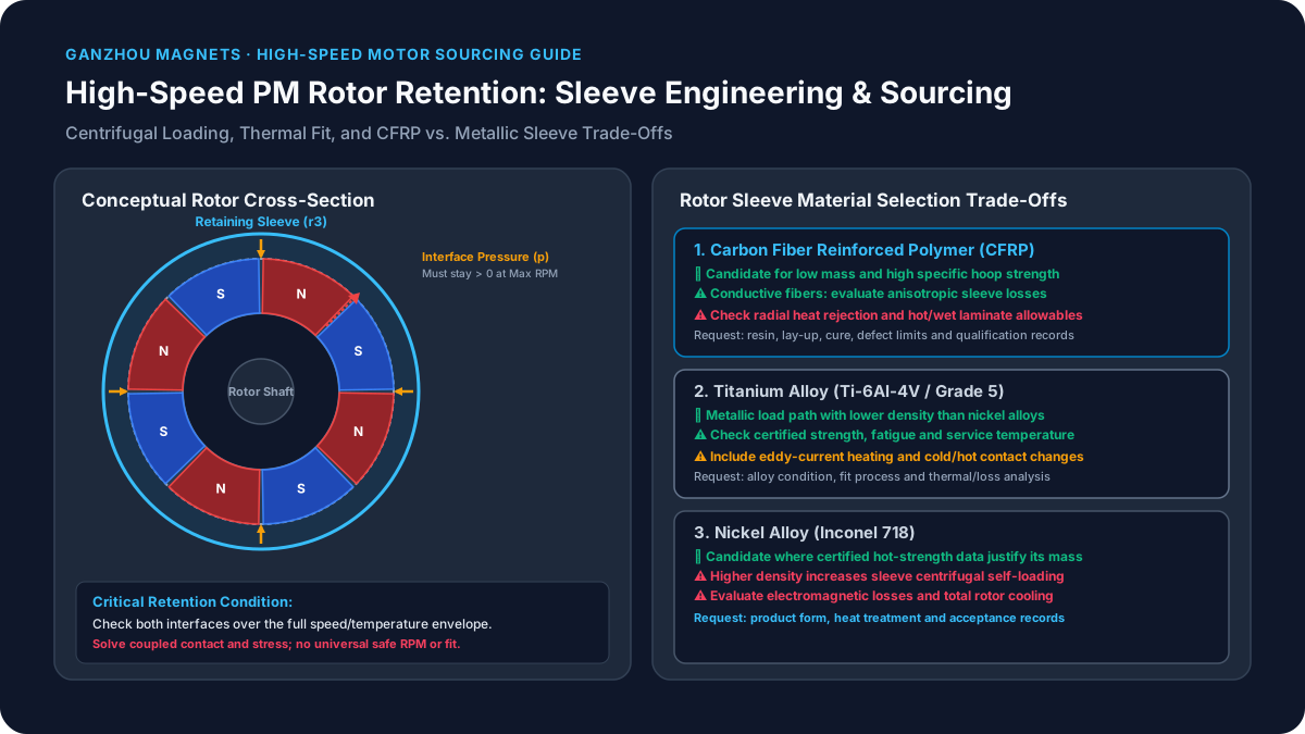
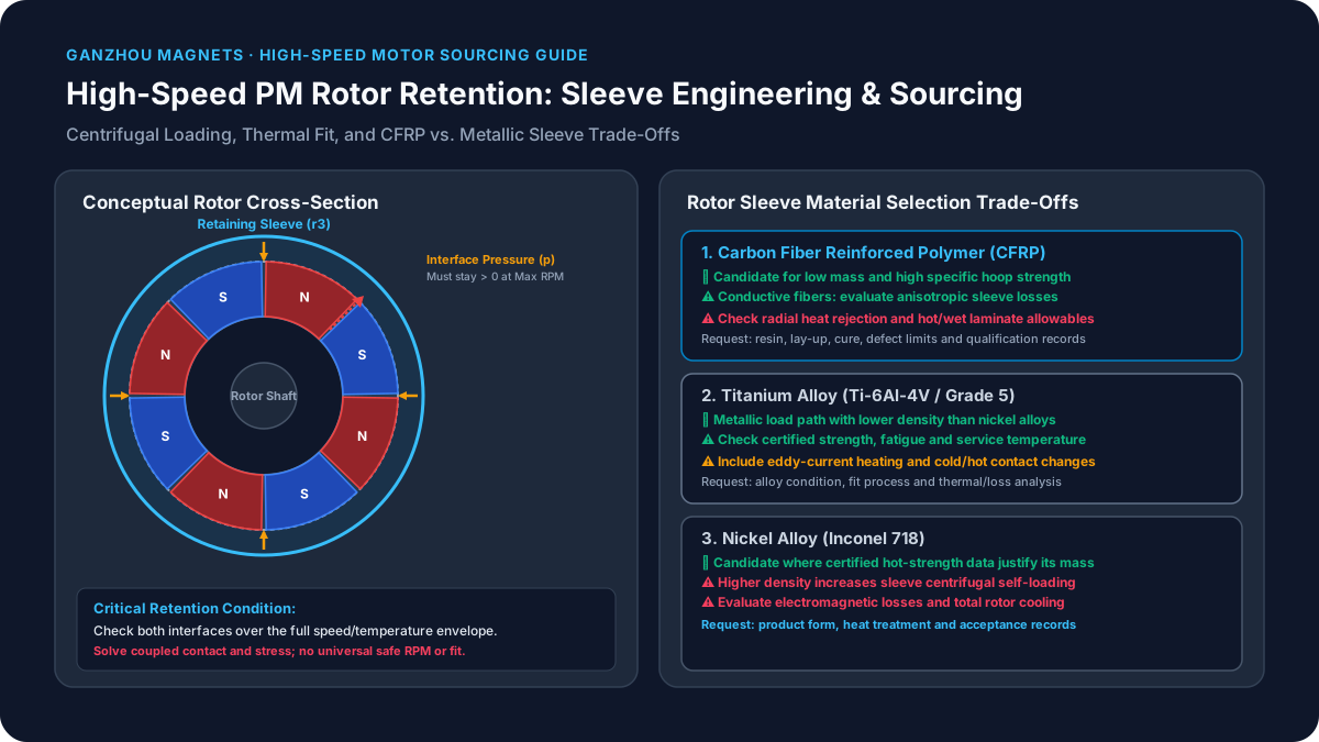
Figure 1: Conceptual rotor cross-section, not a stress contour or test result. The sleeve applies inward contact pressure to the magnet layer. Check contact and material stresses across the complete operating envelope; the illustration is not to scale.
1. Centrifugal Physics: Why Surface PM Rotors Need Retention
Centrifugal loading increases with density and the square of peripheral velocity:
ω = 2π × RPM / 60         [rad/s]
v = ω × r                [m/s]
characteristic stress scale ≈ ρ × v²  [Pa]
Here ρ is density in kg/m³ and r is radius in metres. RPM alone cannot establish sleeve suitability: doubling radius at the same speed increases this stress scale fourfold.
Worked screening example: stress scale, not a failure prediction
For an assumed NdFeB density of 7,500 kg/m³ and a tip speed of 150 m/s:
ρ × v² = 7,500 × 150² = 168,750,000 Pa = 168.75 MPa
RPM at a 30 mm radius = 150 × 60 / (2π × 0.030) ≈ 47,746
This is a characteristic loading scale; it equals hoop stress for an ideal freely rotating thin ring. It is not the local stress in supported magnet tiles and does not predict instant fracture. Tile geometry, shaft contact, adhesive properties, preload, flaws, and temperature determine local stresses. Use supplier material data and an assembly model rather than comparing this scale directly with a generic magnet tensile-strength number.
Adhesives may carry a designed share of load, but room-temperature lap-shear data do not qualify radial retention, peel resistance, or thermal fatigue. Define the sleeve and bondline load paths explicitly.
2. Lamé Thick-Walled Mechanics: Calculating the Required Interference Fit
To prevent the magnet segments from separating from the rotor hub or lifting off during rotation, the sleeve must exert an inward radial contact pressure p against the outer surface of the magnets.
The No-Lift-Off Boundary Condition
The foundational design criterion for high-speed SPM rotors is:
p_interface(ω_max, T_max) ≥ p_residual_min > 0Check both shaft-to-magnet and magnet-to-sleeve interfaces at the relevant combinations of speed and temperature, including cold start, hot operation, and qualification overspeed. The design authority must define the required residual pressure from contact, fretting, tolerance, and material limits. There is no universal 2–5 MPa minimum or 120% overspeed rule for every rotor.
Calculating Contact Pressure (p) from Radial Interference (δ)
Let:
r_1: Inner radius of the permanent magnet layer (rotor shaft outer radius).r_2: Outer radius of the permanent magnet layer (sleeve inner radius before deformation).r_3: Outer radius of the retaining sleeve.δ: Total nominal radial interference (r_2,magnet - r_2,sleeve,ID).E_s, ν_s: Young's modulus and Poisson's ratio of the retaining sleeve.E_m, ν_m: Equivalent elastic modulus and Poisson's ratio of the magnet array (illustrative assumptions:E_m = 160 GPa, ν_m = 0.24; obtain grade-specific data).
For an isotropic sleeve fitted over an ideal continuous magnet ring with a traction-free inner bore, the axisymmetric plane-stress estimate at room temperature is:
p_0 = δ / [ r_2 · ( C_s / E_s + C_m / E_m ) ]Where the geometric compliance factors are:
C_s = (r_3² + r_2²) / (r_3² - r_2²) + ν_s
C_m = (r_2² + r_1²) / (r_2² - r_1²) - ν_m
Static vs. Dynamic Hoop Stress in the Sleeve
For this static, isotropic, internally pressurized sleeve with a free outer surface, the maximum hoop stress occurs at its inner bore:
σ_θ,inner(static) = p_0 · [ (r_3² + r_2²) / (r_3² - r_2²) ]Worked fit example (assumed inputs): Let r1 = 20 mm, r2 = 25 mm, r3 = 26 mm, δ = 0.010 mm radial, Es = 114,000 MPa, νs = 0.34, Em = 160,000 MPa, and νm = 0.24.
Cs = 25.8498; Cm = 4.3156
effective radial compliance = 25 × (Cs/114,000 + Cm/160,000)
                            ≈ 0.006343 mm/MPa
p0 ≈ 0.010 / 0.006343 = 1.58 MPa
σ_θ,inner(static) ≈ 1.58 × 25.5098 ≈ 40.2 MPa
Radial interference is half the diametral interference. This arithmetic is a reproducible static example, not a recommended fit. A real shaft-supported magnet ring has a different inner boundary condition; segmented magnets and bondlines also change compliance. Do not apply the scalar Young's modulus formula to CFRP.
At speed, sleeve self-expansion and magnet/hub expansion interact. The two interface pressures must be solved together with temperature and displacement compatibility; they cannot be obtained by subtracting a generic centrifugal pressure. For metals, check an appropriate combined-stress criterion against temperature-dependent allowables and fatigue limits. For CFRP, check fiber, matrix, and interlaminar failure criteria with laminate-specific knockdowns. The design authority must select safety factors for the application.
3. Thermal Expansion: Check Cold and Hot Fit Limits
For two freely expanding concentric members at the same temperature, a first screening estimate of interference change is:
Δδ_thermal ≈ r2 × (α_inner,effective − α_sleeve,hoop) × ΔTUse the effective outer-radius expansion of the supported magnet/hub assembly, not a single magnet CTE selected without its orientation. Sintered magnets and CFRP can be anisotropic, and shaft restraint changes the result.
Metallic sleeves: possible loss of hot preload
If the sleeve's free bore expansion exceeds the inner assembly's expansion, hot interference decreases. For an illustrative r2 = 25 mm, α_inner = 4.5 × 10⁻⁶/K, α_sleeve = 8.6 × 10⁻⁶/K, and ΔT = 130 K:
Δδ_thermal = 25 × (4.5 − 8.6) × 10⁻⁶ × 130
            = −0.013325 mm = −13.3 µm
That exceeds the 10 µm cold radial interference in the independent static example, warning that this simplified pair could lose contact. Once the predicted interference is negative, the fitted-contact formula no longer applies. Shaft support, actual CTE data, temperature gradients, and rotation must be included before deciding whether a real rotor lifts off.
CFRP sleeves: possible increase in hot stress
A predominantly hoop-wound laminate may expand less circumferentially than the inner assembly. Heating can then increase preload and hoop stress. Check both the minimum cold retention and maximum hot contact stress, using the cured laminate's orthotropic properties. Resin glass-transition temperature, hot/wet strength, creep, and service exposure also constrain the design. Neither metal nor CFRP has a universally safe cold interference.
4. Retaining Sleeve Material Engineering & Procurement Comparison Matrix
Selection rule: Shortlist CFRP for specific strength and mass, titanium for a lighter metallic load path, and Inconel 718 for a hot-strength requirement supported by its certified condition. Then evaluate total rotor loss, heat rejection, and tolerance capability for each candidate. The table is an engineering decision framework, not measured comparative performance or a price quotation.
| Decision criterion | CFRP sleeve | Ti-6Al-4V titanium sleeve | Inconel 718 sleeve | RFQ evidence to request |
|---|---|---|---|---|
| Rotating mass and hoop loading | Low density; hoop performance depends on lay-up | Lower density than nickel alloy; include self-loading | Higher density increases centrifugal self-loading | Geometry, mass, material condition, overspeed stress analysis |
| Strength definition | Laminate failure limits; no metal-style yield value | Temperature-dependent yield, fatigue and fracture limits | Heat treatment and product form strongly affect allowables | Certified minimum properties at service temperature |
| Sleeve eddy currents | Conductive fibers; loss is anisotropic, not automatically zero | Conductive metal; evaluate harmonic losses | Conductive metal; evaluate harmonic losses | Rotor-frame harmonic spectrum and loss model |
| Heat removal | Through-thickness heat conduction can be limiting | Check sleeve, interfaces and air-gap heat transfer | Check sleeve, interfaces and air-gap heat transfer | Thermal network and magnet temperature prediction |
| Thermal fit | Low hoop expansion can increase hot preload | Relative expansion can reduce or increase preload | Relative expansion can reduce or increase preload | Cold/hot contact and tolerance stack-up |
| Fluid and environment | Resin compatibility, moisture and hot/wet aging matter | Check corrosion, coating and joint compatibility | Check corrosion, coating and joint compatibility | Fluid exposure conditions and qualification records |
| Assembly and inspection | Preformed fit or direct winding; inspect laminate defects | Qualified fit process and thin-wall dimensional inspection | Qualified fit process plus heat-treatment traceability | Process limits, NDT method and acceptance criteria |
| Cost and supply | Tooling, laminate qualification and scrap drive total cost | Stock form, machining and inspection drive total cost | Stock condition, machining and inspection drive total cost | Itemized tooling, prototype, production and test quote |
The Special Metals alloy 718 bulletin provides condition-dependent material data, explicitly distinguishing typical values from specification limits. Apply that distinction to every candidate. A raw-fiber tensile value is not a cured-sleeve allowable; an alloy family name is not a heat-treatment certificate.
For a quote comparison, use the drawing and procurement checklist to keep the acceptance basis consistent across suppliers.
5. The Electromagnetic Dilemma: Parasitic Eddy Current Losses and Skin Depth
While a metallic sleeve provides isotropic mechanical strength, predictable thermal behavior, and straightforward shrink-fitting, its electrical conductivity introduces a critical electromagnetic penalty.
Physics of High-Speed Rotor Eddy Currents
When the rotor spins inside a slotted stator, the rotating magnetic field is not perfectly smooth. High-frequency spatial and temporal harmonic fields are induced by:
- Stator slot openings (permeance harmonics): Frequency
f_slot = N_slots · (RPM)/(60). For a 48-slot stator operating at 30,000 RPM,f_slot = 24,000 Hz. - Inverter Pulse-Width Modulation (PWM) harmonics: Use the actual carrier and sideband spectrum at the intended operating points.
- Stator winding MMF distribution harmonics: 5th, 7th, 11th, and 13th spatial harmonics.
According to Faraday's law of induction and Lenz's law, these fluctuating magnetic flux densities ((dB)/(dt)) induce circular eddy currents inside any conductive sleeve. For a thin conducting plate under a sinusoidal field, with thickness well below skin depth, the classical volumetric loss scaling is:
p_eddy ≈ (π² · f² · B_peak² · t_sleeve²) / (6 · ρ_e)Where:
fis the harmonic electrical frequency (Hz).B_peakis the peak amplitude of the harmonic flux density ripple in the sleeve (T).t_sleeveis the radial thickness of the sleeve (m).ρ_eis the electrical resistivity of the sleeve material (Ω·m).
This plate approximation shows sensitivity to frequency, field amplitude, thickness, and resistivity. Cylindrical sleeve current paths, end effects, shielding, and multiple harmonics require an electromagnetic model; the equation is not a general rotor-loss predictor.
The Skin Depth (δ_s) Phenomenon
In metallic sleeves, alternating eddy currents concentrate near the outer surface facing the stator bore. The electromagnetic skin depth δ_s is governed by:
δ_s = √( ρ_e / (π · f · μ_0 · μ_r) )For an illustrative titanium calculation with assumed ρ_e = 1.78 × 10^-6 Ω·m and µ_r = 1.0, exposed to a 20 kHz harmonic:
δ_s = √( (1.78 × 10⁻⁶) / (π · 20,000 · 4π × 10⁻⁷ · 1.0) ) ≈ 4.75 × 10⁻³ m = 4.75 mmFor an assumed 1 mm wall, this example has t < δ_s, so the field can penetrate much of the thickness. Skin depth alone does not establish loss in watts or whether a sleeve will overheat. Harmonic amplitude, current paths, geometry, and cooling remain necessary inputs.
Jun et al.'s sleeve-structure study addresses eddy-current loss reduction in high-speed SPMSMs. For procurement, request both sleeve and magnet loss estimates under the intended stator and inverter spectrum, followed by a thermal assessment against the magnet's hot demagnetization curves.
6. CFRP Thermal Trade-Off: Low Sleeve Loss Does Not Ensure Cool Magnets
Carbon fibers conduct electricity, and laminate conductivity depends on fiber direction, lay-up, and contacts between fibers. CFRP may reduce sleeve losses relative to a metallic candidate, but zero eddy-current loss is not a universal material property. Slotless stators still have winding and inverter harmonics; magnet losses do not automatically vanish.
Through-thickness thermal conductivity can also limit radial heat removal. A one-dimensional, thin-layer screening estimate is:
ΔT_layer ≈ q″ × t / k_radialFor hypothetical inputs q″ = 10,000 W/m², t = 0.0015 m, and k_radial = 0.5 W/(m·K), the layer temperature drop is 30 K. This assumes steady, uniform radial heat flux and neglects curvature, interface resistance, axial paths, and convection. It is not an observed temperature rise or proof that a real rotor is 30 K hotter than a metal-sleeved design.
Engineering decision sequence
- Calculate rotor-frame harmonics for the actual stator, winding, speed, and inverter duty.
- Compare sleeve and magnet losses for each candidate. Electrically isolated magnet segmentation can reduce relevant eddy-current paths; select segment size from the model rather than a fixed 2–4 mm rule.
- Check radial, axial, and shaft heat paths with realistic contact resistance and cooling conditions.
- Verify hot demagnetization margin using supplier curves at the predicted magnet temperature and worst reverse field.
- Check sleeve stress, contact, resin limits, and rotor dynamics at the same operating conditions.
For hot or chemically aggressive service, evaluate both metal compatibility and composite resin qualification. A continuous metal tube does not by itself provide hermetic sealing: end joints and leak-test requirements must be specified.
7. Manufacturing & Interference Fit Assembly Methods
Transitioning a sleeved rotor design into production requires controlled assembly processes. Brittle magnets cannot tolerate edge impact, uneven axial pressing loads, or localized contact peaks.
Method 1: Thermal shrink-fitting of metallic sleeves
Calculate the clearance required from the fit tolerance stack and handling allowance, then qualify the heating cycle. For illustration only, a free titanium sleeve with r = 25 mm, assumed α = 8.6 × 10⁻⁶/K, and a uniform temperature change from 20°C to 300°C expands radially by:
Δr = r × α × ΔT = 25 × 8.6 × 10⁻⁶ × 280
    = 0.0602 mm = 60.2 µm
This arithmetic is not a recommended assembly temperature. The magnet, coating, adhesive, and fixture need independent temperature limits; irreversible demagnetization can occur well below Curie temperature. Specify measured temperature/time limits, controlled insertion, and cooling. Any chilling process also needs condensation and thermal-shock controls; do not assume cryogenic immersion or rapid quenching is acceptable.
Method 2: Qualified press-fitting of preformed sleeves
Use a supported insertion fixture and a validated lead-in geometry, surface finish, and lubrication system. Record force versus displacement and reject abnormal insertion behavior. Adhesive compatibility, cure chemistry, bondline thickness, coating damage, and sleeve-edge stresses must be verified for the actual materials. Generic roughness or taper values do not establish an acceptable process.
Method 3: Direct filament winding or towpreg placement
Controlled winding tension can introduce preload without sliding a finished sleeve over the magnets. Cure shrinkage, fiber angle, resin system, voids, hot/wet properties, and rotor temperature history affect the final assembly. Require a qualified winding/cure specification and laminate inspection plan. Shi et al.'s carbon-fiber sleeve parameter-design paper is a relevant published design reference; it is not evidence that a supplier's own winding process is qualified.
8. Sourcing & Turnkey Procurement: Sintered Tiles vs. Tested Assemblies
Industrial buyers face a build-versus-buy decision. Compare each offer against the same drawing revision and evidence package:
| Scope | Loose tiles and separately sourced sleeve | Complete rotor assembly |
|---|---|---|
| Interface ownership | Buyer coordinates magnet OD, sleeve ID, hub and coating stack | Assembly supplier owns the agreed interface stack |
| Process qualification | Buyer qualifies bonding, fitting or winding | Require the supplier's applicable qualification records |
| Inspection | Individual component reports do not establish assembled retention | Require assembled dimensions, balance and specified NDT records |
| Prototype tests | Buyer arranges analysis correlation and spin qualification | Define whether tests are included, outsourced or excluded |
| Commercial terms | Allocate rework and interface disputes explicitly | Define warranty scope, exclusions and acceptance responsibility |
| Cost comparison | Include tooling, handling, yield, assembly and inspection | Separate tooling, unit price, test cost and delivery scope |
A hypothetical tolerance example shows why interface ownership matters: a 15 µm increase in magnet diameter adds 7.5 µm of radial interference if sleeve ID is unchanged. Whether that is acceptable depends on the original fit and local contact stresses; it does not imply a fixed percentage increase or inevitable fracture.
A complete-assembly purchase transfers only the responsibilities written into the agreement. Ask for evidence of dimensional capability, balance equipment, qualified sleeve processes, and outsourced test scope. This guide does not establish Ganzhou Magnets production yield, in-house spin capability, or an automatic warranty transfer.
To scope a project, request a drawing and sourcing review with the required supply boundary: magnets only, matched components, or a qualified assembly quotation.
9. High-Speed PM Rotor Drawing & Procurement Specification Checklist
Use this checklist when preparing an RFQ and quality agreement. The motor design authority must approve numerical acceptance limits.
- Operating envelope: Specify continuous, maximum and qualification speeds, dwell times, speed cycles, cold-start conditions, peak magnet temperature, cooling and fluid exposure. Identify the application standard and agreed test plan; do not assume 120% for two minutes applies universally.
- Sleeve specification: Identify alloy/product form/heat treatment or fiber/resin/lay-up/cure revision. Request lot traceability and temperature-dependent certified allowables. Set composite void and fiber-volume limits from the qualified process.
- Fit and dimensions: State radial versus diametral interference at a reference temperature, min/max sleeve ID and magnet OD, datum system, form, runout, coating thickness and bondline allowance. Assign finish limits from contact and process requirements.
- Contact and stress verification: Require coupled cold/hot/overspeed analysis of both interfaces, local segment-edge stresses, fatigue and appropriate metal or laminate failure criteria. Agree minimum residual pressure and maximum allowable stress for this rotor.
- Magnetic and thermal margins: Supply the duty cycle, stator/inverter harmonic spectrum and cooling assumptions. Require hot demagnetization curves, reverse-field margin and estimated sleeve/magnet losses.
- Balance and rotor dynamics: For rigid-behavior rotors, specify the applicable ISO 21940-11 edition, agreed balance grade, correction planes, test speed and allowable residual unbalance. Flexible behavior needs a suitable rotor-dynamics and balancing procedure. No uncontrolled removal of structural sleeve material.
- Inspection and release records: Define material-appropriate NDT, calibration, defect acceptance, sample size and lot coverage. Agree flux-mapping conditions and harmonic acceptance where required. Separate dimensional/balance checks from contained overspeed and any destructive burst qualification; assign owners and pass criteria.
10. Frequently Asked Questions (FAQ)
Q1: Can retaining adhesive replace a high-speed rotor sleeve?
Not on the basis of a lap-shear datasheet alone. Validate radial loading, peel, thermal fatigue, coating adhesion, magnet integrity and failure containment for the entire assembly. There is no universal 12,000 RPM cutoff: rotor diameter, magnet mass, temperature and joint geometry change the load. Where the design relies on a sleeve, qualify the adhesive's role without treating it as equivalent containment.
Q2: What is the maximum safe tip speed for titanium versus CFRP?
Neither material has a universal safe tip speed. Specific strength helps shortlist candidates, but magnet loading, wall geometry, prestress, fatigue, temperature and defects determine the assembly limit. Use metal allowables for the specified condition and cured-laminate allowables for CFRP, then qualify the rotor at its defined operating and test envelope.
Q3: How do we manage magnet heating under a CFRP sleeve?
Calculate losses and heat paths together. Electrically isolated magnet segmentation can reduce some eddy-current loops; shaft or axial cooling may provide other heat paths. Validate those options against mechanical and manufacturing constraints. A GBD process label or UH/EH suffix does not guarantee a stated coercivity at 150°C: require the supplier's hot demagnetization curves and check the actual load line and reverse field.
Q4: Does a metallic sleeve shield magnets from stator harmonics?
It can redistribute harmonic fields and losses, depending on conductivity, thickness, frequency and geometry. Reduced magnet loss may be accompanied by greater sleeve loss. Compare total rotor loss and resulting component temperatures; neither shielding nor stator-jacket cooling alone guarantees acceptable magnet temperature.
Q5: Which balance grade should procurement specify?
Agree the grade and balancing procedure with the motor design authority. ISO 21940-11 addresses rotors with rigid behavior; it does not make G1.0 or G2.5 mandatory for all high-speed motors. For a selected grade G in mm/s:
e_per [µm] = 1,000 × G / ω
At 60,000 RPM: ω ≈ 6,283.19 rad/s
For an assumed G1.0 target: e_per ≈ 0.159 µm
U_per [g·mm] = rotor mass [kg] × e_per [µm]
This is permissible mass eccentricity, not an identical surface-runout tolerance. Allocate residual unbalance to correction planes and check the rotor's dynamic behavior. Finishing or balancing corrections must preserve minimum structural sleeve thickness and the qualified laminate; universal sleeve grinding is not an acceptable default.
Q6: Can SmCo magnets use a thinner sleeve than NdFeB?
Higher-temperature magnetic capability does not establish a thinner sleeve. For assumed densities of 8.4 and 7.5 g/cm³, equal geometry and speed give a mass-proportional centrifugal-load ratio of 8.4 / 7.5 = 1.12. That illustrative 12% increase is not a universal contact-pressure ratio. Recalculate fit, local stresses, thermal expansion and grade-specific magnetic performance for the chosen material.
Request a High-Speed PM Rotor Drawing & Sourcing Review
Send Ganzhou Magnets your rotor drawing, speed and temperature envelope, stator/inverter information, sleeve preference, and qualification requirements. Request a feasibility and sourcing review, with an itemized quote identifying the proposed supply scope, required validation, and any third-party tests.
Sources & References
- Shi, T., Wu, J., Yan, D., Cao, Y., & Guo, L. (2026) — Parameter Design of Carbon Fiber Sleeve for High-Speed Permanent Magnet Machines. IEEE Transactions on Industry Applications, 62(3), 4707–4718. Relevant to carbon-fiber sleeve parameter design. Bibliographic identity was checked through DOI metadata; this guide does not reproduce the paper's experimental results.
- Jun, H.-W., Lee, J., Lee, H.-W., & Kim, W.-H. (2015) — Study on the Optimal Rotor Retaining Sleeve Structure for the Reduction of Eddy-Current Loss in High-Speed SPMSM. IEEE Transactions on Magnetics, 51(3), 1–4. Relevant to sleeve structure and eddy-current loss reduction. Bibliographic identity was checked through DOI metadata; no numerical loss result from this paper is asserted here.
- Special Metals Corporation — INCONEL alloy 718 technical bulletin, SMC-045 (September 2007). Material condition, physical properties, thermal properties and mechanical-property tables. Typical bulletin data are not procurement specification limits or rotor qualification evidence.
Evidence and review limits: Published and editorially reviewed November 01, 2026. The calculations use stated assumptions and classical screening models; they are not measured rotor performance or approved drawing limits. Numerical fit, balance, NDT, and overspeed criteria require agreement for each application. Review by November 2027, or earlier if the cited material data, applicable balancing requirements, or project operating envelope changes. Hardware release requires validated analysis and a project-approved prototype qualification plan.
Categories
p) from Radial Interference (δ)Static vs. Dynamic Hoop Stress in the Sleeve3. Thermal Expansion: Check Cold and Hot Fit LimitsMetallic sleeves: possible loss of hot preloadCFRP sleeves: possible increase in hot stress4. Retaining Sleeve Material Engineering & Procurement Comparison Matrix5. The Electromagnetic Dilemma: Parasitic Eddy Current Losses and Skin DepthPhysics of High-Speed Rotor Eddy CurrentsThe Skin Depth (δ_s) Phenomenon6. CFRP Thermal Trade-Off: Low Sleeve Loss Does Not Ensure Cool MagnetsEngineering decision sequence7. Manufacturing & Interference Fit Assembly MethodsMethod 1: Thermal shrink-fitting of metallic sleevesMethod 2: Qualified press-fitting of preformed sleevesMethod 3: Direct filament winding or towpreg placement8. Sourcing & Turnkey Procurement: Sintered Tiles vs. Tested Assemblies9. High-Speed PM Rotor Drawing & Procurement Specification Checklist10. Frequently Asked Questions (FAQ)Q1: Can retaining adhesive replace a high-speed rotor sleeve?Q2: What is the maximum safe tip speed for titanium versus CFRP?Q3: How do we manage magnet heating under a CFRP sleeve?Q4: Does a metallic sleeve shield magnets from stator harmonics?Q5: Which balance grade should procurement specify?Q6: Can SmCo magnets use a thinner sleeve than NdFeB?Sources & ReferencesMore Posts

NdFeB Magnet Machining Tolerances: Cost Drivers and DFM Guidelines
NdFeB magnet machining tolerances guide for DFM: compare ±0.1mm, ±0.05mm, and ±0.01mm cost drivers, coating stack-ups, RFQ actions, and buyer quote limits.


April 2026 U.S. Magnet Tariff Update: Sintered NdFeB Has a Different Surcharge Path
What U.S. importers should do now that the 2026 temporary import surcharge excludes HTS 8505.11.0070 sintered NdFeB magnets, while the broader 2026 Section 301 tariff on permanent magnets remains in force.

Neodymium Magnet Quality Control & Testing: The Complete IQC Guide for Buyers
A comprehensive guide to Incoming Quality Control (IQC) for NdFeB magnets. Learn how to test magnetic flux, verify coatings with HAST/SST, and audit Chinese suppliers.