
Permanent Magnet Structural Adhesive Bonding for Electric Motor Rotors: CTE Anisotropy, Coating Compatibility, Lap-Shear Physics, and Procurement Specifications
Plan permanent magnet adhesive bonding for motor rotors: compare coatings, thermal mismatch and joint tests. Use the RFQ checklist to request a drawing review.
Published and editorially reviewed: November 11, 2026. Written for electromechanical motor designers, automotive traction powertrain leads, robotic actuator engineers, magnetics manufacturing engineers, and B2B procurement directors sourcing sintered Neodymium-Iron-Boron (NdFeB) and Samarium-Cobalt (SmCo) permanent magnets for bonded rotor assemblies.
Permanent magnet adhesive bonding in surface-mounted permanent magnet (SPM) rotors transfers electromagnetic torque from magnet tiles to the rotor core. In electric vehicles, servo drives, drone propulsion units, and industrial compressors, a detached magnet can contact the stator, fracture, and seize the motor. This guide addresses that failure mechanism without claiming how frequently it occurs in the field.
Select the magnet coating, adhesive, bondline, and qualification test together. Room-temperature catalog lap-shear strength alone cannot establish rotor retention. Sintered NdFeB has direction-dependent thermal expansion, while rotor substrates expand differently. Thermal mismatch, centrifugal loading, torque, and environmental exposure must all enter the joint qualification.
For coated magnets, structural adhesives contact the protective finish rather than the NdFeB alloy. Surface contamination, weak coating adhesion, uncontrolled gaps, incomplete cure, or irreversible demagnetization during oven curing can compromise the assembly before service.
This guide connects joint physics to coating selection, process controls, and a procurement specification. Its calculations are illustrative screening examples, not measured customer results or approved design limits. For magnet dimensions, chamfers, and coating requirements, request a drawing review with Ganzhou Magnets.
Scope, Assumptions, and Engineering Boundaries
- Target Motor Architectures: Surface-Mounted Permanent Magnet (SPM) synchronous rotors, external-rotor brushless DC (BLDC) outrunners, linear permanent magnet tracks, and adhesive-assisted interior permanent magnet (IPM) slot potting.
- Magnetic Materials Covered: Sintered NdFeB; the procurement workflow also applies to sintered SmCo, but the NdFeB expansion example must not be transferred to SmCo without its material data.
- Substrate Materials: Electrical silicon steel lamination stacks (e.g., M270-35A, NO20), solid rotor steels (low-carbon AISI 1018 or alloy steel 4140), and aircraft-grade aluminum hubs (6061-T6, 7075-T6).
- Operational Boundaries: Example temperatures and dimensions illustrate the method. Specify actual magnet and bondline temperatures, overspeed, duty cycle, and fluids for each motor; winding hotspot temperature is not automatically the joint temperature.
- Commercial & RFQ Scope: Global engineering and procurement guidance for design-for-manufacturing (DFM), adhesive screening, and incoming quality control (IQC). Standards cited here describe coupon testing, not universal rotor acceptance values. Application-specific analysis and physical assembly qualification remain necessary.
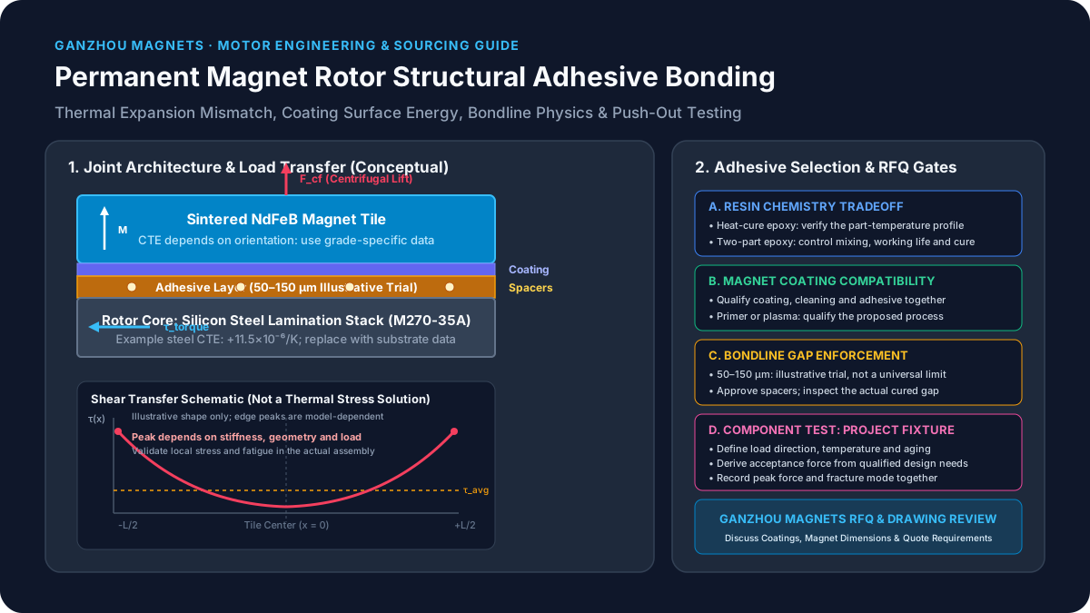
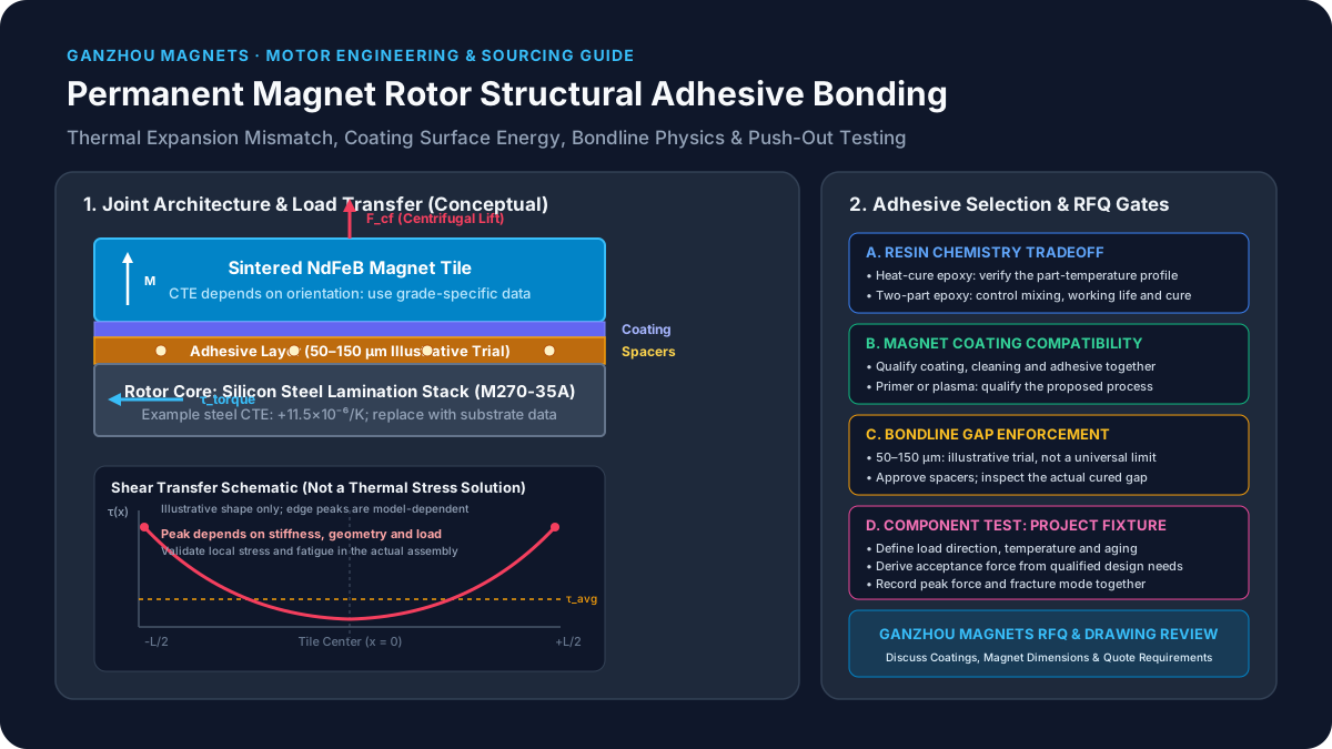
Figure 1: Original conceptual schematic, not to scale or a test result. Coating adhesion, thermal mismatch, controlled adhesive thickness, and component tests are separate qualification gates. The 50–150 μm bondline is an illustrative trial range requiring adhesive-specific approval.
1. The Physics of Rotor Adhesive Joints: Anisotropic CTE & Shear-Lag Mechanics
Anisotropic Thermal Expansion of Sintered NdFeB
A single expansion coefficient can hide a material-direction mismatch. For a specific published example, Arnold Magnetic Technologies' N48M datasheet gives typical coefficients of +7 × 10⁻⁶/K parallel and −1 × 10⁻⁶/K perpendicular to orientation, measured between 20°C and 200°C. These are grade-specific typical values, not guaranteed limits for every NdFeB magnet.
For a radially oriented tile, the axial direction lies transverse to the local orientation. Curved tiles with parallel rather than radial orientation require a local coordinate transformation; establish the magnetic axis on the drawing before using material coefficients.
Illustrative screening calculation: assume a 50 mm axial tile, an electrical-steel expansion coefficient of 11.5 × 10⁻⁶/K, the transverse magnet coefficient above, and a temperature rise from 20°C to 140°C. The steel coefficient is an example input to replace with the actual substrate data.
Differential free strain = (alpha_steel - alpha_magnet) × delta_T
                        = [11.5 - (-1.0)] × 10^-6 × 120
                        = 0.00150 = 0.15%

Center-to-end free displacement = (L / 2) × differential strain
                                = 25 mm × 0.00150
                                = 0.0375 mm = 37.5 micrometres
This is the relative movement of unconstrained materials referenced at the tile center. It is not the actual adhesive displacement or stress: bonded parts deform together, and the joint redistributes load. Cure shrinkage, temperature-dependent modulus, and the effective stress-free temperature also affect residual stress. A heat-cured assembly may already carry stress when cooled to room temperature.
Shear-Lag Mechanics: Why Bond Length Alone Does Not Set Capacity
In a Volkersen-type shear-lag model, the adhesive transfers load between adherends with different axial stiffnesses. Stress can concentrate near the overlap ends rather than remaining uniform over the footprint. Thermal mismatch can reverse the shear direction across the center; it must not be represented by a universal, same-sign U-shaped stress curve.
The practical consequence is that doubling overlap area need not double fatigue resistance. Adhesive stiffness, thickness, adherend stiffness, geometry, and temperature determine the transfer length. Curved magnet joints, lamination stacks, peel stresses, and viscoelastic behavior need a model appropriate to their construction. There is no general threefold or fourfold edge-stress multiplier.
Screen candidate toughened adhesives using the actual coating and substrate. Consider edge chamfers and controlled fillets where geometry permits, then verify their effects rather than assuming they eliminate stress concentration. Elongation at break alone does not establish fracture toughness, creep resistance, or durability.
Multiaxial Forces: Centrifugal Lift, Torque Shear, and Radial Preload
For a thin magnet segment on an inner SPM rotor, a useful first approximation to average centrifugal traction is:
F_cf = m × r_cg × omega^2
sigma_cf = F_cf / A_bond ≈ rho × t_m × r_cg × omega^2
omega = 2 × pi × RPM / 60
With illustrative inputs of density 7,600 kg/m³, thickness 0.005 m, center-of-mass radius 0.040 m, and speed 18,000 RPM, the result is approximately 5.4 MPa. This assumes a thin segment and a footprint consistent with the mass calculation. It is average normal traction, not lap-shear stress or a local peel-stress prediction. Sleeve support, adhesive voids, curved geometry, and load concentration change the actual stress field. In an external rotor, centrifugal loading may press magnets toward the housing instead; retain the actual load direction in the analysis.
Average torque-induced shear can be screened as tau_avg = T / (n × r × A_bond), where n is the number of equally loaded tiles and r their effective force radius. Do not substitute pole count if each pole contains multiple tiles. Unequal magnetic loading and manufacturing variation require additional consideration.
Compare these separate demands with qualified hot, aged joint properties and a project-approved combined-load model. A room-temperature coupon value cannot establish the margin. If retention remains uncertain, evaluate mechanical assistance using the high-speed PM rotor sleeve retention guide; tip speed alone does not define a universal sleeve threshold.
2. Magnet Surface Coatings & Interfacial Adhesion Chemistry
For a coated magnet, the load path includes rotor substrate, adhesive, coating, and magnet. A strong resin cannot compensate for a weak coating-to-magnet interface. Specify the finish and surface preparation as part of the bonded system, including storage and the time between cleaning, activation, and dispensing.
Coating Compatibility Matrix
The matrix is a qualification plan, not a ranking based on assumed surface-energy values. Chemistry, contamination, aging, coating cure, and pretreatment can change adhesion within the same nominal finish.
| Coating Finish | Bonding Question | Failure to Investigate | Evidence to Request Before Approval |
|---|---|---|---|
| Cathodic epoxy e-coat | Does the adhesive wet and adhere to the fully cured coating? | Coating peel, incomplete coating cure, or interfacial release | Actual coated coupons, coating cure records, hot and aged joint tests |
| Ni-Cu-Ni plating | Is the plated surface clean and compatible with the selected resin? | Oil contamination, adhesive release, or plating separation | Cleaning specification; comparison of direct bonding and supplier-approved primer or plasma |
| Electroless nickel (Ni-P) | Does phosphorus content and surface condition affect the selected process? | Adhesive release or damage from aggressive pretreatment | Finish identification and bonded trials using the intended production finish |
| Passivated zinc | Is the conversion/passivate layer a stable bonding surface? | Weak boundary layer, corrosion, or coating separation | Passivate identity, storage history, and humidity/fluid-conditioned joints |
| Phosphate or other thin conversion finish | Is corrosion protection adequate after assembly? | Underfilm corrosion or bond degradation after storage | Defined handling interval, protection method, and relevant environmental tests |
| Parylene C | Can an approved activation process bond the deposited polymer surface? | Adhesive release or coating-to-magnet separation | Coating and adhesive supplier agreement on treatment and its usable time window |
Clean nickel can support useful adhesion; it is not inherently a low-energy, nonpolar surface. Likewise, bonding to cured epoxy e-coat does not guarantee covalent cross-linking. Avoid generic dyne-number pass limits unless correlated with joint performance. A wetting check can screen process drift but cannot measure coating adhesion or rotor life.
Do not abrade through a corrosion barrier or introduce an unqualified solvent. Validate cleaning and any primer or plasma treatment on representative coated magnets, then test after the intended storage interval and environmental exposure.
Record Failure Mode Alongside Peak Load
A cohesive adhesive fracture leaves resin on both surfaces, but it can still occur below the required load. An adhesive interfacial fracture leaves one interface relatively clean and can indicate preparation, contamination, cure, or material-compatibility problems. Coating separation or magnet fracture requires investigation of both the substrate and the test fixture.
Photograph the fracture surfaces and estimate the area of each mode; mixed failure is possible. Failure appearance alone does not prove supplier fault. Approval requires the specified load, durability, and acceptable failure-mode criteria together. Request actual lot evidence rather than relying on a generic plating guarantee.
3. Structural Adhesive Chemistry Selection Matrix
Select a named product and process after screening the chemistry family. Service-temperature labels, glass transition temperature, and room-temperature strength describe different properties. None supplies an allowable for a hot rotor joint by itself.
| Adhesive System | Process Advantage | Main Qualification Question | RFQ Evidence |
|---|---|---|---|
| One-part heat-cure epoxy | No mixing step; controlled thermal cure | Can the magnet, coating, fixture, and bondline withstand the full cure profile? | Part-temperature cure record, hot strength, and magnetic checks |
| Two-part toughened epoxy | Potential for lower-temperature assembly | Are mix ratio, dispensing, working life, and full cure controlled? | Mixing/dispensing limits and strength after the proposed cure |
| Structural acrylic | Rapid handling strength may suit short takt times | Is the exact finish compatible with the activation and cure system? | Coated-part tests, open time, and thermal/fluid aging |
| Anaerobic retaining compound | Useful in suitable close-fitting assemblies | Will actual gap and surface activity permit full cure? | Approved geometry, activator requirement, and geometry-specific test data |
| Light plus secondary-cure system | Accessible areas can be fixed quickly | Does the shadowed bondline receive a validated secondary cure? | Light dose, secondary-cure record, and shadow-zone verification |
| Heat-activated film or tape | Can provide controlled material placement | Is it designed for this rotor topology and gap? | Supplier-defined processing window and application-specific retention evidence |
For an example of the last approach, Henkel's magnet-bonding tape announcement describes an expanding epoxy film for fixing magnets and compensating manufacturing tolerances in electric motors. The announcement does not establish an allowable for the specific SPM joint being sourced.
Require the technical datasheet revision and test conditions behind every strength value. Check substrate, preparation, gap, cure, test temperature, and aging before comparing numbers. Retaining-compound tests on cylindrical specimens are not directly interchangeable with tensile single-lap coupon results. Fluid compatibility must identify the actual oil or coolant formulation and exposure conditions.
4. Bondline Thickness Engineering & Dispensing DFM
Specify a Qualified Window, Not a Universal Optimum
A 50–150 μm trial bondline can be a starting discussion for a close-fitting joint if the adhesive supplier permits it. Some systems and geometries require different gaps. There is no universal inverted-U strength curve or minimum thickness that establishes a safe rotor.
A very thin local gap can leave inadequate adhesive coverage where coating roughness, lamination steps, or part distortion consume the space. A thick gap can change joint compliance, cure behavior, void formation, and creep. In a fixed stator envelope, additional nonmagnetic thickness can also change the magnetic circuit and clearance. Quantify that effect for the actual design rather than assigning a fixed percentage of flux loss.
Control Spacers and Clamping Together
Use fixture stops or adhesive-supplier-approved spacer beads where suitable. Bead diameter sets a local spacing scale; it does not guarantee whole-tile flatness. Bead concentration, dispersion, contact pressure, adhesive flow, and coating damage need validation. Avoid adding an arbitrary percentage of glass to a commercial resin: it changes the supplied formulation and may affect dispensing, cure, or strength.
Verify the cured gap using qualified cross-sectioning or another agreed inspection method at defined positions, including corners and the center. Record the range across multiple parts. A nominal dispenser setting or a single spacer diameter is not evidence of achieved bondline uniformity.
Dispensing, Coverage, and Fillet Management
Choose dispensing equipment compatible with viscosity, fillers, working life, and the approved gap. Trial dot, bead, or parallel-line patterns on representative geometry and inspect coverage and trapped air. No pattern guarantees complete air removal.
Define adhesive mass or volume, placement, assembly motion, clamping, and allowable open time. Specify a maximum fillet envelope against the rotor clearance drawing. If excess material must be removed, validate the operation so it does not disturb uncured alignment, damage the coating, or leave debris. Inspection should confirm both coverage and clearances after cure.
For a sourcing discussion, send the intended coating, gap, cure profile, and annual volume for a drawing review. These inputs help separate the magnet quotation from the adhesive-process qualification work.
5. Thermal Demagnetization Risks During Adhesive Oven Cure Cycles
Heat cure must satisfy the adhesive process while preserving magnetic performance. Review actual magnet temperature, fixture magnetic return path, orientation, and the grade's temperature-dependent demagnetization curves. Oven air temperature alone may miss part-temperature lag, overshoot, or a local exotherm.
Arnold's cited N48M sheet reports a coercivity temperature coefficient of −0.60%/°C over 20–100°C. Do not extrapolate that coefficient linearly to 150°C or use it as a universal NdFeB law. The complete demagnetization curve and operating load line determine whether irreversible loss occurs, as explained in the NdFeB thermal demagnetization and load-line guide.
There is no universal rule that cure temperature must remain 25°C below a grade rating. Nor does an SH, UH, or EH suffix automatically approve a cure cycle. A keeper fixture may improve the magnetic circuit, but its actual geometry and hot condition must be evaluated.
Record the temperature profile at representative parts through heating, dwell, and cooling. Compare magnetic measurements before and after the complete process at the same reference temperature, using an agreed measurement method and acceptance limit. This separates reversible temperature effects from permanent changes. If bonding unmagnetized parts is proposed, assess the equipment, fixture access, and saturation evidence needed for post-assembly pulse magnetization.
6. Sintered NdFeB Mechanical Tolerancing & DFM for Bonding
The magnet drawing, coated dimensions, rotor surface, and fixture stack-up jointly determine the cured joint. Tightening one magnet tolerance does not automatically control the assembly gap. Use the following drawing review to identify dimensions that need supplier confirmation.
| Parameter | Drawing or Inspection Requirement | Why It Matters |
|---|---|---|
| Finished tile thickness | State whether dimensions include coating; allocate the stack-up | Controls rotor envelope and available adhesive space |
| Bonding-face profile | Define the actual flatness or arc-profile datum and measurement method | Identifies local high spots and unsupported gaps |
| Edges and chamfers | Specify permitted edge break and chipping outside the active footprint | Balances handling robustness, bonded area, and magnetic geometry |
| Coating thickness and condition | Give permitted variation and inspect bonding faces | Coating variation contributes to the gap and weakest-interface risk |
| Surface texture | Agree a finish compatible with coating integrity and the adhesive process | Roughness alone cannot establish adhesion |
| Magnetic axis and assembly orientation | Mark polarity or reference features away from the bonding face | Prevents orientation errors without damaging the protective finish |
For cost and process discussions, use the NdFeB magnet machining tolerances and DFM guide. Treat quoted tolerances as drawing-specific commitments requiring supplier confirmation, not universal machining capabilities.
7. Mechanical Push-Out & Lap-Shear Testing Protocol
Separate Coupon Screening from Component Qualification
ISO 4587:2003 describes tensile lap-shear testing of rigid-to-rigid bonded standard specimens. Its abstract explicitly excludes design information. ASTM D1002 is another metal single-lap screening method; neither standard makes a custom rotor push-out fixture compliant merely because results are expressed in MPa.
Use representative coatings, substrates, and cure conditions for screening coupons, and record all departures from the chosen method. Test actual bonded components separately using a documented fixture, loading direction, and acceptance plan. A rotor may need radial retention and fatigue evidence as well as axial push-out results.
Component-Level Axial Push-Out Procedure
- Define the specimen and fixture. Support the rotor core while leaving the selected tile's axial exit path clear. A pusher engages the tile end face in the axial direction without clamping it radially against the core. Document contact location, alignment, clearances, and how the fixture avoids magnet crushing or unintended bending.
- Agree rate and conditioning. State crosshead speed, temperature, dwell, and whether the test occurs hot or after cooling. A proposed 1 mm/min is a project fixture setting to qualify, not an ISO requirement for rotors. Document thermal cycling, fluids, and exposure duration where relevant.
- Report force and displacement. Record peak load in newtons and the force-displacement curve. Calculate apparent push-out stress as
F_peak / A_bond, with area in mm² to obtain MPa. State the geometric or measured area convention. Friction and fixture effects mean this result is not a pure adhesive material property. - Set acceptance before testing. Derive project thresholds from loads, margins, geometry, environmental aging, and supporting validation. Define sample count, lot sampling, baseline comparisons, permissible failure modes, and treatment of invalid tests. There is no universal 18 MPa room-temperature or 8 MPa hot acceptance limit.
- Record traceability. Include magnet lot, coating lot, adhesive lot and shelf life, preparation, dispense/cure record, fixture revision, temperature, calibrated equipment, and fracture photographs.
Arithmetic example only: if a project has independently established a 1,000 N axial acceptance load for a 500 mm² footprint, its reporting equivalent is 1,000 / 500 = 2 MPa. This conversion does not establish the required load or prove radial retention. Compare unconditioned, hot, and aged results under the same agreed area and fixture convention.
8. Sourcing & Engineering RFQ Drawing Checklist
Use this checklist to make supplier proposals comparable and assign the remaining qualification work:
- Magnet grade and magnetic circuit: Include orientation, geometry, operating temperatures, hot demagnetization curves, and cure-state magnetic conditions.
- Coating specification: Identify finish, finished thickness, permitted defects, preparation, storage, and evidence of coating adhesion.
- Rotor substrate: Identify alloy or lamination finish, profile, surface preparation, and contamination controls.
- Drawing datums: Specify finished dimensions, profile, chamfers, polarity identification, and the assembly tolerance stack-up.
- Approved adhesive: State exact product, datasheet revision, mix/cure controls, shelf life, and qualification status; family names are insufficient.
- Bondline and spacers: Give the qualified gap range, permitted spacer system, clamping method, and cured-gap inspection locations.
- Coverage and clearance: Define permissible voids, coverage evidence, fillet envelope, and post-cure rotor clearances.
- Magnetic process checks: Record actual part temperatures and before/after magnetic acceptance at a common reference condition.
- Mechanical acceptance: Specify load direction, fixture revision, temperature, rate, minimum force, sampling, and acceptable failure modes.
- Durability conditions: Define cycle limits, dwell/ramp, fluid identity, duration, and hot versus cooled testing according to the service environment.
- Lot traceability and change control: Require records and agreed requalification after coating, resin, preparation, geometry, or cure-process changes.
- Commercial ownership: Separate magnet supply, assembly processing, destructive sampling, tooling, and final design approval in the quote.
9. Frequently Asked Questions (FAQ)
Q1: Why can a rotor fail when the adhesive catalog quotes 35 MPa shear strength?
The catalog value applies to specified specimens, preparation, cure, and test conditions. A rotor introduces different coatings, temperature, normal traction, thermal mismatch, and fatigue. Check the actual datasheet conditions and qualify representative joints; do not apply a universal strength-derating percentage.
Q2: Can Ni-Cu-Ni plated magnets be bonded directly without primer?
Possibly. Clean nickel is not inherently unsuitable, but the actual finish and adhesive must be tested together. Compare supplier-approved cleaning, direct bonding, and any primer or plasma process after realistic aging. Switching to epoxy e-coat does not automatically solve the interface problem.
Q3: What is the risk of oven-curing pre-magnetized NdFeB tiles?
The hot magnetic operating point may enter the irreversible region of the demagnetization curve. Evaluate the actual grade, shape, magnetic circuit, and full part-temperature profile. Grade suffixes and keeper plates require validation; neither gives automatic approval.
Q4: Do glass beads guarantee a 100 μm bondline without weakening it?
No. Beads can help control local spacing, but dispersion, clamp pressure, part profile, and formulation matter. Use an approved spacer system and inspect the cured joint. Supplier agreement and joint tests are needed before modifying a commercial adhesive.
Q5: When is a retaining sleeve needed as well as adhesive?
When project analysis and qualification cannot establish adequate retention with adhesive alone, or the design's containment requirements call for mechanical assistance. Speed, radius, magnet thickness, temperature, aging, and load sharing matter together. There is no universal safe tip-speed cutoff.
Q6: Does cohesive failure mean the joint passed?
Only if the joint also meets the required load, conditioning, and failure-mode criteria. Cohesive fracture below the acceptance force fails the requirement. Photograph mixed failure and investigate coating separation or magnet fracture before assigning a cause.
Request a Permanent Magnet Rotor Bonding & DFM Review
Send Ganzhou Magnets your magnet and rotor drawings, coating requirement, joint temperature range, speed profile, quantity, and proposed acceptance test. Discuss supplier-confirmed magnet dimensions, coating options, and quotation requirements, with adhesive-process qualification and final rotor approval assigned in your project plan.
Sources & References
- International Organization for Standardization — ISO 4587:2003: tensile lap-shear strength of rigid-to-rigid bonded assemblies. Supports the coupon-test scope and its limitation concerning design information. It does not specify custom rotor push-out acceptance loads.
- Arnold Magnetic Technologies — N48M sintered NdFeB datasheet, revision 210802. Grade-specific typical thermal data and demagnetization curves. Its stated measurement intervals matter; these values are not Ganzhou production measurements.
- Henkel — Magnet-bonding tape for electric motors, April 20, 2020. Manufacturer example of expanding epoxy film for magnet fixation and gap filling. It supplies no component-level SPM qualification data.
Editorial review notes: Published and reviewed November 11, 2026, for global engineering and procurement use. Review again by November 2027 or when cited material data or relevant test methods change. The numerical examples are reproducible screening calculations, not field-failure statistics, supplier guarantees, or measured rotor qualification results.
Author

Categories
More Posts

N35 vs N52 Neodymium Magnets: The Hidden Costs of Over-Specification
A comprehensive guide for engineers and procurement teams comparing N35 and N52 neodymium magnets. Learn how to avoid the hidden costs of over-specification.

Custom Magnets for Electric Motors and EV Applications: Selection Guide
Engineering guide for selecting NdFeB and SmCo magnets for BLDC, PMSM, and DC motors. Covers grade selection, demagnetization analysis, thermal management, and sourcing from prototype to volume production.

Surface Gauss vs. Pull Force: How to Specify NdFeB Magnet Strength in RFQs
Use this RFQ checklist to specify NdFeB magnet strength with surface Gauss, pull force, BH(max), test conditions, supplier QA checks, and drawing notes.